
Can you divide this model axially to use cell tallies like you would in CSG?
Response: Certainly! This can be done in the CAD geometry itself in Cubit or, in the case of OpenMC, using CSG cells to section the DAGMC universe containing the CAD model into different regions.
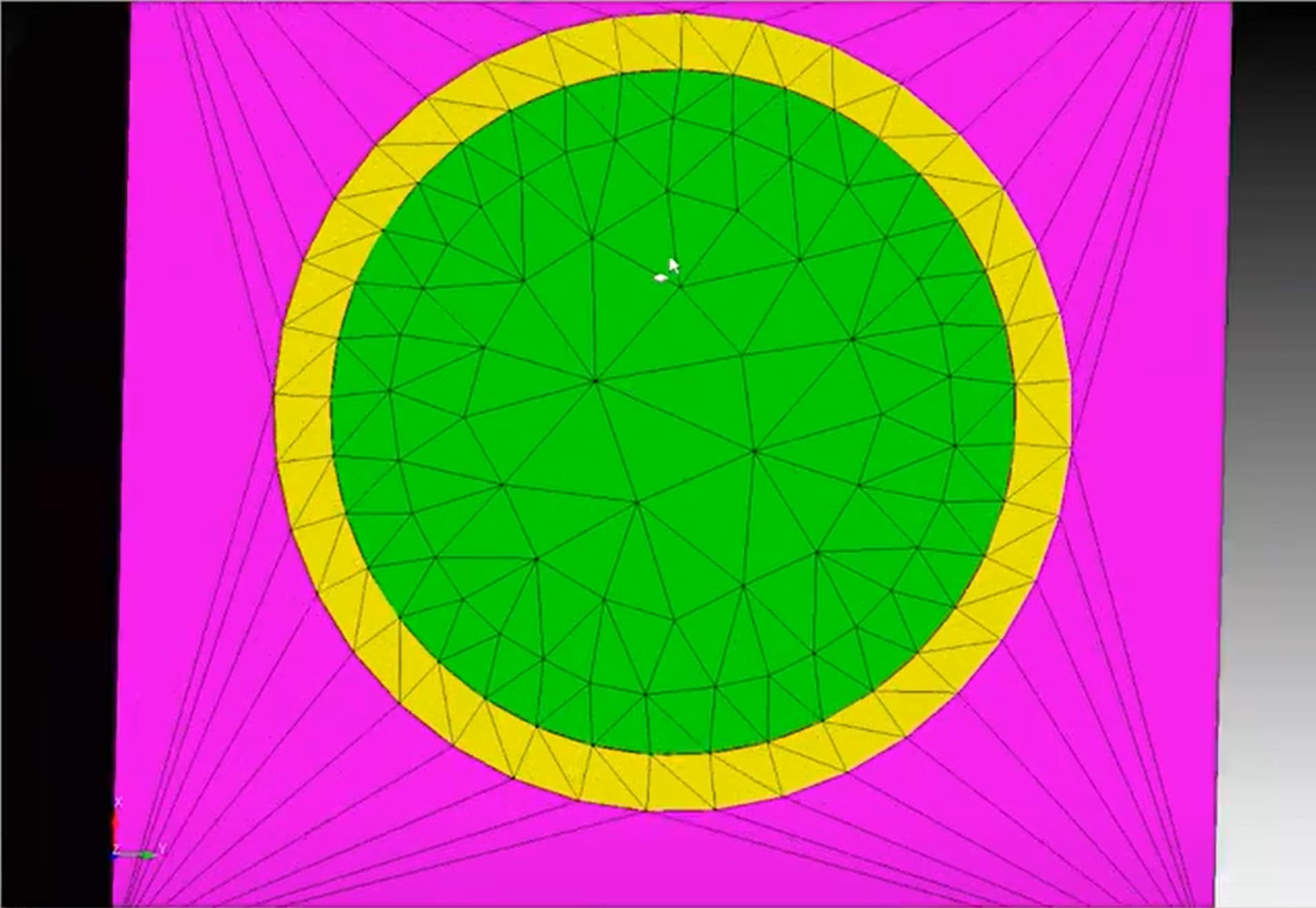
The coarse mesh generated looks very counter-intuitive to someone used to finite elements or similar methods, are there any best practices as to what a “good” DAGMC mesh looks like?
Response: That’s a really good point. This is very counterintuitive to finite elements, because what we mostly care about is minimizing the farthest distance from the CAD analytic surface to the triangle faces & edges, because that is what’s going to affect our tally estimators in simulation of particle transport.
This center (green) surface here provides us with fairly-evenly sized triangles, and then the outer surface has high-aspect ratio triangles, in a kind of fan-like structure, and really the important part for us is that we have a good representation of the volume – by nature of having enough triangle edges on the circular surfaces. Note that this is coarser than you would want to use in a real simulation.
To put some quantitative support behind this, consider the following charts that compare the two schemes’ ability to represent a cylinder. Here use the same mesh-sizing input values, varying the requested Deviation Angle.
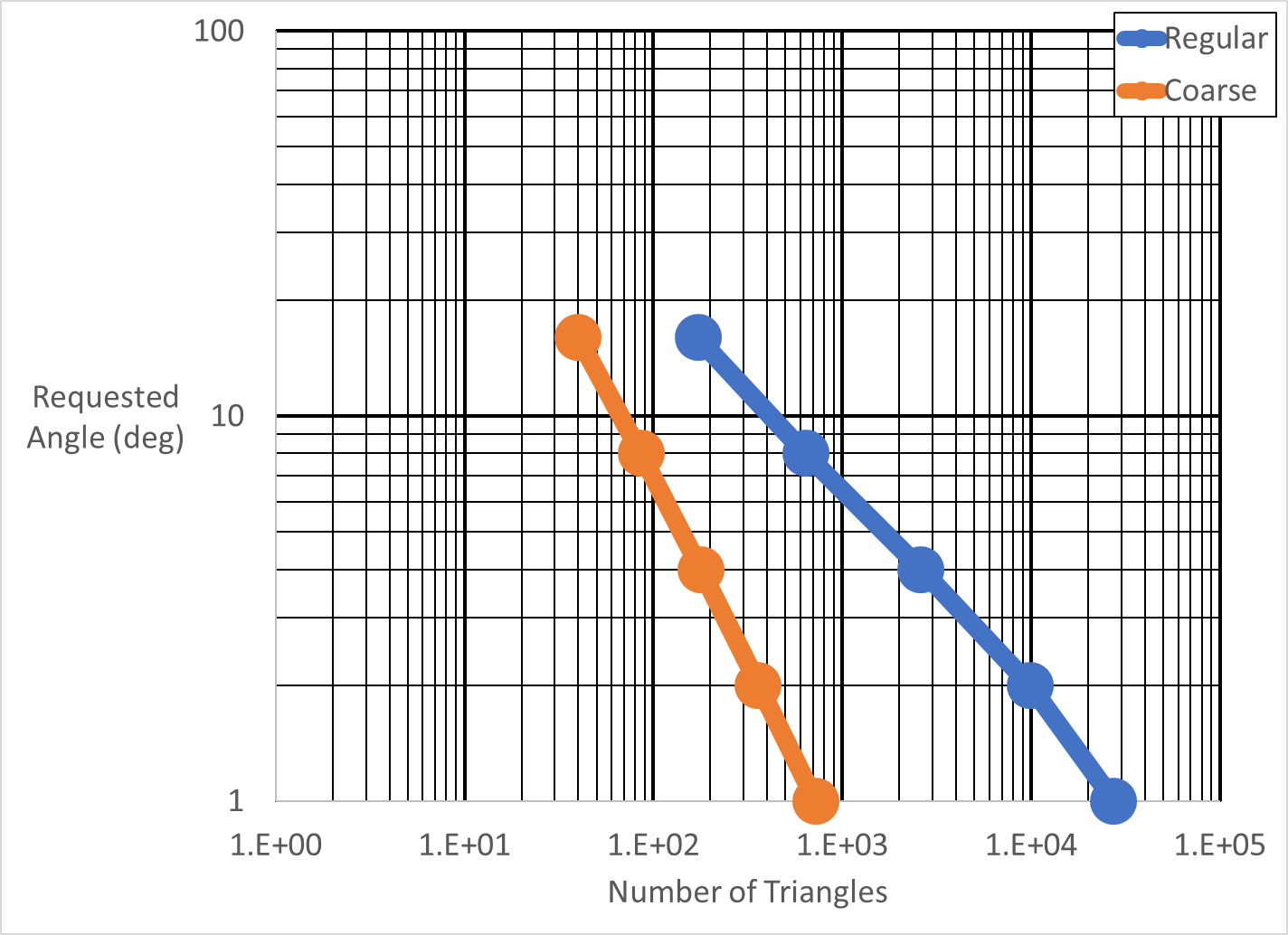
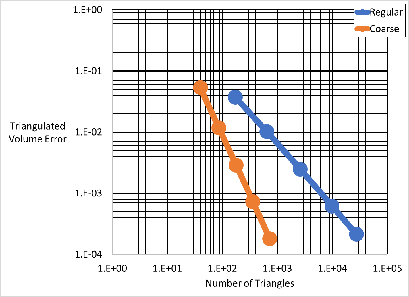
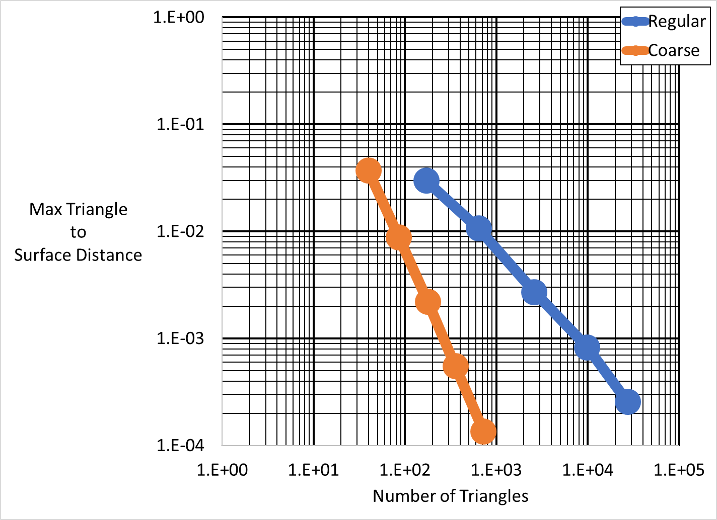
Note that the coarse scheme appears to converge in the two error metrics at a rate of \mathcal{O}(1/N^2) while the regular mesh scheme appears to converge at a rate of only \mathcal{O}(1/N). This means that for large numbers of triangles the coarse mesh scheme may require (several) orders of magnitude fewer triangles, potentially leading to a huge cost savings.
Are there any forbidden characters in cubit material names?
Response: Some caution should be given prior to using Unicode characters such as Ä, ¿, ¶, Ѫ, and typesetting characters such as will not evaluate (so \n will not insert a new line).
We don’t have comprehensive testing for character sets, so I recommend testing on a small model - exporting to your desired format and verifying that it exports as you expect.
Are you able to assign an OpenMC universe by name as a material in cubit?
Response: We’ve interpreted this question as asking: “Can you give a name for the resulting OpenMC universe containing the CAD model?” In which case, no. Cubit is really only responsible for generating the DAGMC model and, at this point in time, has no knowledge of additional geometry in the Monte Carlo model that may interact with the DAGMC model once it has been exported.
Is there an option in OpenMC to export geometry in form of CAD, on which Cubit can create/generate mesh for other application such as fuel performance/CFD calculation?
Response: In short, no, not right now. What does exist is that we can do this with MCNP: the ability to import MCNP geometry into CAD has also been integrated as well. So we can get CSG into CAD using that format. But for OpenMC we don’t yet support that And we’ll cover all this in more detail in another webinar.
How would you get the 3-D flux, fission, or energy deposition if you are only meshing the surfaces?
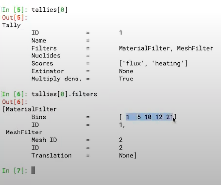
Response: So we can define user defined tallies for OpenMC models. And so if we look at this tally objects, we have a tallies XML file, you can look at that in its raw form, but it’s maybe not readily informative. Essentially, what the XML file contains is a regular mesh over the entire model, with 200 voxels in each each direction. This tally that we defined has both a material filter and a mesh filter on it, so it’s tallying into separate data sets based on the material that particles are going through, as well as the different mesh voxel that it’s going through.
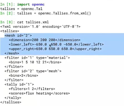
And then two different scores are scored as well, both the flux in the heating. And if we look at the filters we can see the material filter where it’s sectioning the materials out over the different material ids listed here. So that’s kind of the short version, we can also post a lot of the example notebooks that will cover like for OpenMC specific.
Is there any complete tutorial or documentation available on this currently available? I want to perform neutronics simulations, which involve calculating flux distributions and power distributions leading to temperature profiles. Then, I want to transfer this information to Cad software to perform further thermal analysis, extract temperature profiles, and calculate power distributions and reverse flux calculations. Finally, I plan to reintegrate the results back into OpenMC for iterative analysis.
Response: For the DAGMC model generation workflow we are currently in the process of creating tutorials for the Cubit side of things and for using DAGMC geometry and OpenMC there are a number of example notebooks available to go over how to apply these things in more detail than we had time for in the webinar. We’ll post links to those on our form after the webinar.
Also, one of our attendees suggested:
Cardinal might do what you need.
https://cardinal.cels.anl.gov/
While using CAD geometry in Cubit, it sometimes creates virtual volumes that overlap with real volumes. These overlaps are not removable. How should one approach this situation?
Response: Virtual geometry should only ever be created by specific user-issued commands - so I would wait to create any virtual geometry until just prior to meshing (i.e., after all real operations are completed).
Follow-up: I have been importing my geometry as an obj file and the first command I use is create volumes surface all noheal, to be able to mesh them. This command then creates real and virtual volumes. I take this is not the optimal approach?
Response: OBJ is a facetted geometry format, while Cubit does have some capabilities for facet-based geometry these capabilities are not as comprehensive or robust as the standard ACIS geometry kernel. You can verify which engine (facet or ACIS) is being used on a given volume by looking at the Engine property in the Properties Page:
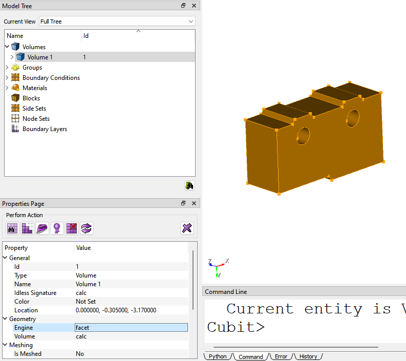
So an optimal approach would be to export a “standard” CAD model (e.g., STEP) from your CAD tool and import this into Cubit.
If Cubit has all surfaces, is it always necessary to mesh a model to run OpenMC DAGMC model?
Response: Yes, it currently is necessary. The H5M file is a mesh-based format so the triangles are going to need to be present for that. Once that H5M file exists DAGMC just ingests the mesh – DAGMC doesn’t have any built-in mesh generation capability. Part of the value of using Cubit for mesh-generation purposes is that using its built-in imprint and merge capabilities can guarantee watertight meshes - a necessity for these particle transport codes - and you can also use its various CAD cleanup / verification utilities to fix errors in the CAD model.
There are potentially hundreds of surfaces that need to be defined as reflecting for sector models in fusion. Is there a better way to capture these than manually defining which can be error prone?
Response: Yes! You can use Cubit’s built-in extended parsing command syntax. This allows you to execute commands such as:
sideset 1 surface all with y_coord<1e-6
You could also use the Python API to develop a sophisticated method for identifying surfaces:
sideset_surfaces = my_awesome_surface_finder()
cubit.cmd( f"sideset 1 surface {cubit.get_id_string( sideset_surfaces )}" )