
I’d like to share with the community my preferred workflow for building Sculpt meshes. Here’s an outline, into which I’ll dive deeper in this post:
- If data is gathered from MRI-, CT-, or Surface-scan sources – use native processing tools (e.g. VGStudio Max, Avizo, GeoMagics) to construct quality STL data. Use these tools to heal and repair STL as much as possible.
- Import model (as either facet (e.g. STL, OBJ) or CAD Brep (e.g. STEP)) into Coreform Cubit
- Set the current working directory to a temporary (aka “scratch”) directory just for Sculpt
- Use Coreform Cubit to become familiar with geometry and to create an initial input-file for Sculpt
- Instead of running Sculpt from Cubit, I like to run Sculpt from the command line - using the input file.
- Explore Sculpt meshing options by using the command-line “Help” syntax
-
sculpt.exe -h: to print a summary of all commands -
sculpt.exe -h <parameter>: to print detailed information regarding a specific Sculpt parameter
-
- Edit the input-file in a text editor, with the commands I’ve gathered from step 5
- Execute Sculpt from the command line
sculpt.exe --num_procs <num_processes> -i <input_file>
- Recombine the partitioned Exodus files that Sculpt outputs (one per processor) using
epuepu.exe -auto <outputName>.e.<num_processes>.0- If it helps you remember,
epuis an acronym for the Latin phrase: E Pluribus Unum which means “out of many, one” and is a motto of the USA.
- Import the resulting
<outputName>.efile into Coreform Cubit
Deeper dive
Step 1: Preprocess STL geometry (if applicable).
Coreform Cubit was not developed for specific applications in MRI-, CT-, or surface-scan data-acquisition. Use tools that are purpose built for these applications - your hardware likely comes with scan-data processing software. Here are some examples of software that you might use for pre-processing and cleaning your STL file.
- VGStudio Max
- Amira-Avizo
- GeoMagic Design X
- 3D Slicer (Free & Open-Source!)
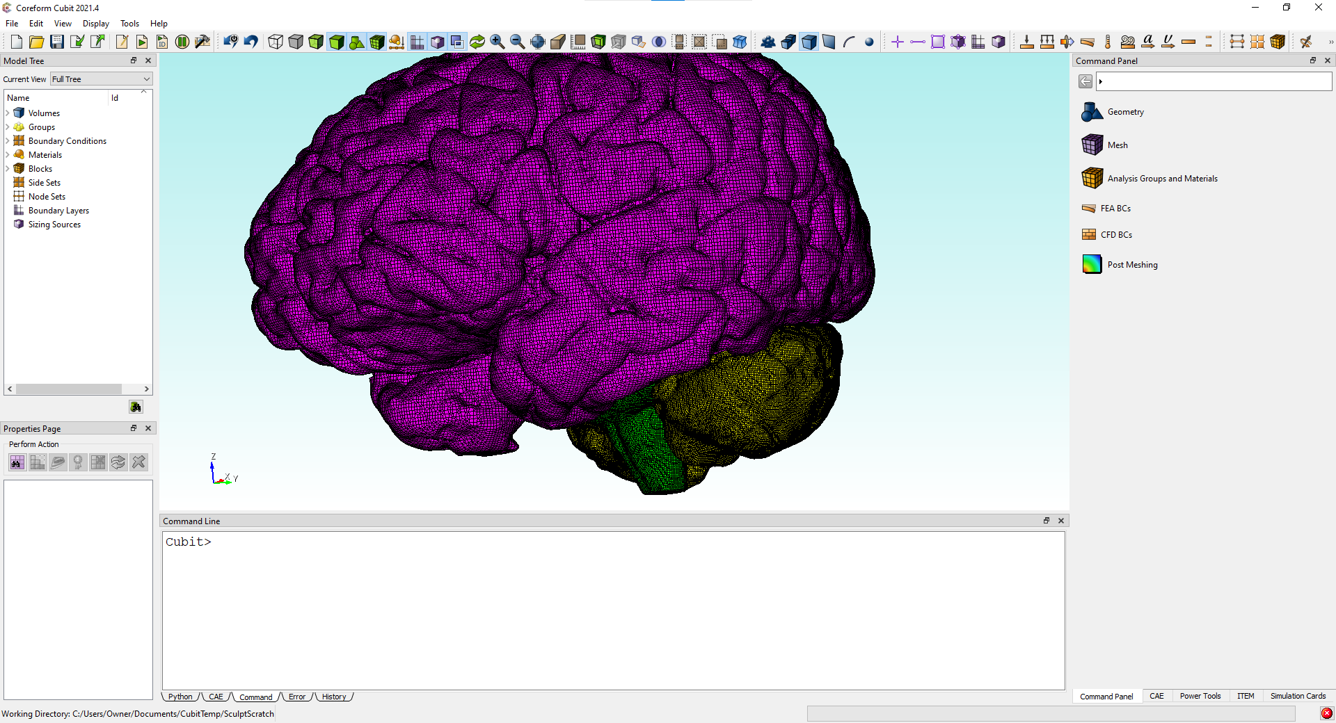
Step 2: Importing into Coreform Cubit
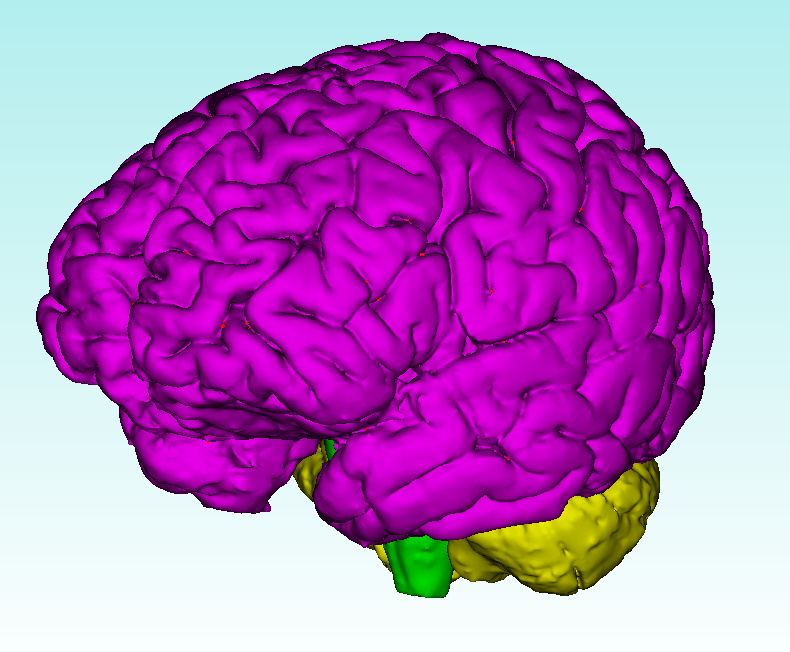
Let’s work with an STL assembly of a brain that I found on GrabCad:
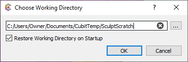
Step 3: Set the current working directory to a temporary (aka “scratch”) directory just for Sculpt
I personally have a CubitTemp directory and a subdirectory called SculptScratch – CubitTemp is within my user documents directory:
cd "C:\Users\Owner\Documents\CubitTemp\SculptScratch"- or via the GUI under
File -> Set Directory:
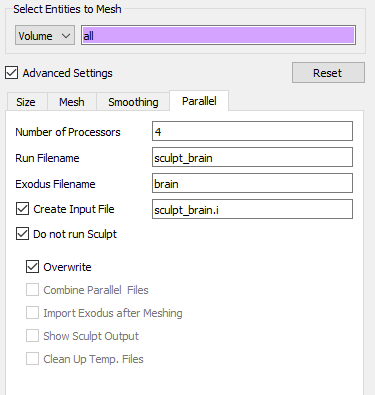
Step 4: Prepare initial Sculpt settings and generate input file
I like to preview my mesh sizing, using a coarse mesh (I can refine this later)

Then I skip through most of the advanced options. The important thing is to specify a few settings under the Parallel tab. Namely:
- Provide relevant filenames
- Check the box next to
Create Input File - Check the box next to
Do not run Sculpt
For example, here’s what I might choose for this brain problem:
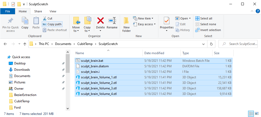
This will create several files within the current directory
-
sculpt_brain.bat- A batch file that provides a command line argument with all parameters set in the GUI
- I don’t use this file
-
sculpt_brain.i- A text file with parameter-value pairs that can be passed into Sculpt using the
-iparameter
- A text file with parameter-value pairs that can be passed into Sculpt using the
-
sculpt_brain.diatom- This is essentially an “assembly” of STL files (or other inputs) that tells Sculpt which STL files to build a mesh on, and what materials (blocks) to assign the elements contained within each volume.
- If you make new STL files (say from multiple scans, or additional cleanup) you don’t need to run Coreform Cubit to build a Sculpt mesh on these volumes. Simply move the new STL files to your Sculpt temp directory and change the Diatom file to point to your new STL files
-
sculpt_brain_Volume_#.stl- One STL for each volume, these are referenced by the Diatom file
File contents
Here are the contents of the first three files listed above:
-
sculpt_brain.bat"C:\Program Files\Coreform Cubit 2021.4\bin\sculpt.exe" -j 4 -x 39 -y 48 -z 39 -t -77.166900 -u -69.968400 -v -86.810250 -q 78.833100 -r 122.031600 -s 69.189750 -e brain -d sculpt_brain.diatom -
sculpt_brain.i(note that$is the comment character$ Input file created: Wed May 19 23:42:04 2021 BEGIN SCULPT nelx = 39 nely = 48 nelz = 39 xmin = -77.166900 ymin = -69.968400 zmin = -86.810250 xmax = 78.833100 ymax = 122.031600 zmax = 69.189750 exodus_file = brain diatom_file = sculpt_brain.diatom END SCULPT -
sculpt_brain.diatomdiatoms package 'Volume_1' material 1 insert stl FILE = 'sculpt_brain_Volume_1.stl' endinsert endp package 'Volume_2' material 2 insert stl FILE = 'sculpt_brain_Volume_2.stl' endinsert endp package 'Volume_3' material 3 insert stl FILE = 'sculpt_brain_Volume_3.stl' endinsert endp package 'Volume_4' material 4 insert stl FILE = 'sculpt_brain_Volume_4.stl' endinsert endp enddia
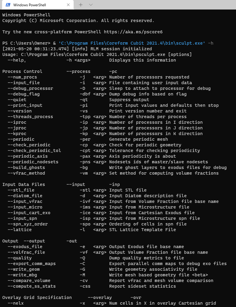
Step 5: Explore Sculpt meshing options by using the command-line “Help” syntax
- Use
sculpt.exe -hto get a concise list of options
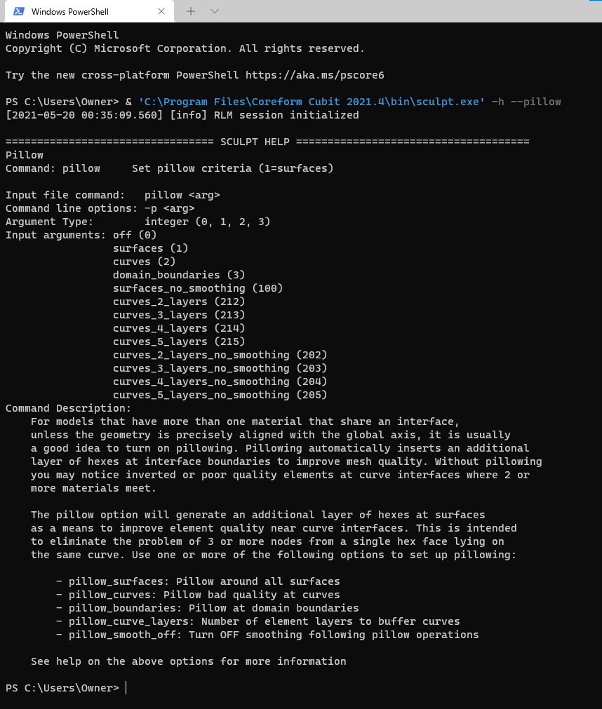
- Use
sculpt.exe -h <option>to get detailed information about an option. For example, let’s say we want infomration about the--pillowoption:-
sculpt.exe -h --pillow
-
Step 6: Edit the input-file in a text editor
At the end I might have a file that looks like this:
$ Input file created: Wed May 19 23:42:04 2021

BEGIN SCULPT

  xmin = -80
  ymin = -70
  zmin = -90
  xmax = 80
  ymax = 130
  zmax = 70
  exodus_file = brain
  diatom_file = sculpt_brain.diatom

  $ My Parameters
  cell_size = 4
  pillow = 1
  adapt_type = vfrac_difference
  adapt_threshold = 0.25
  adapt_levels = 2
  gen_sidesets = geometric_surfaces
  compare_volume
END SCULPT
Step 7: Execute Sculpt from the command line
Make sure to navigate to the Sculpt temporary directory! Then execute Sculpt using the following syntax pattern:
sculpt.exe --num_procs 8 -i sculpt_brain.i
Step 8: Recombine the partitioned Exodus files that Sculpt outputs
The resulting output mesh will be split into 8 parts – one part for each process that we used. Specifically we will have the following files:
brain.e.8.0brain.e.8.1brain.e.8.2brain.e.8.3brain.e.8.4brain.e.8.5brain.e.8.6brain.e.8.7
We want to merge these files into a single file: brain.e which we do via the epu executable:
epu -auto brain.e.8.0
The -auto flag will automatically capture the necessary input data by passing it any one of the partial Exodus files as input.
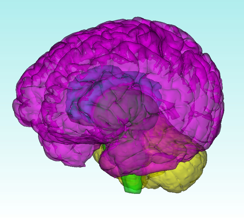
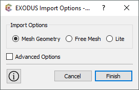
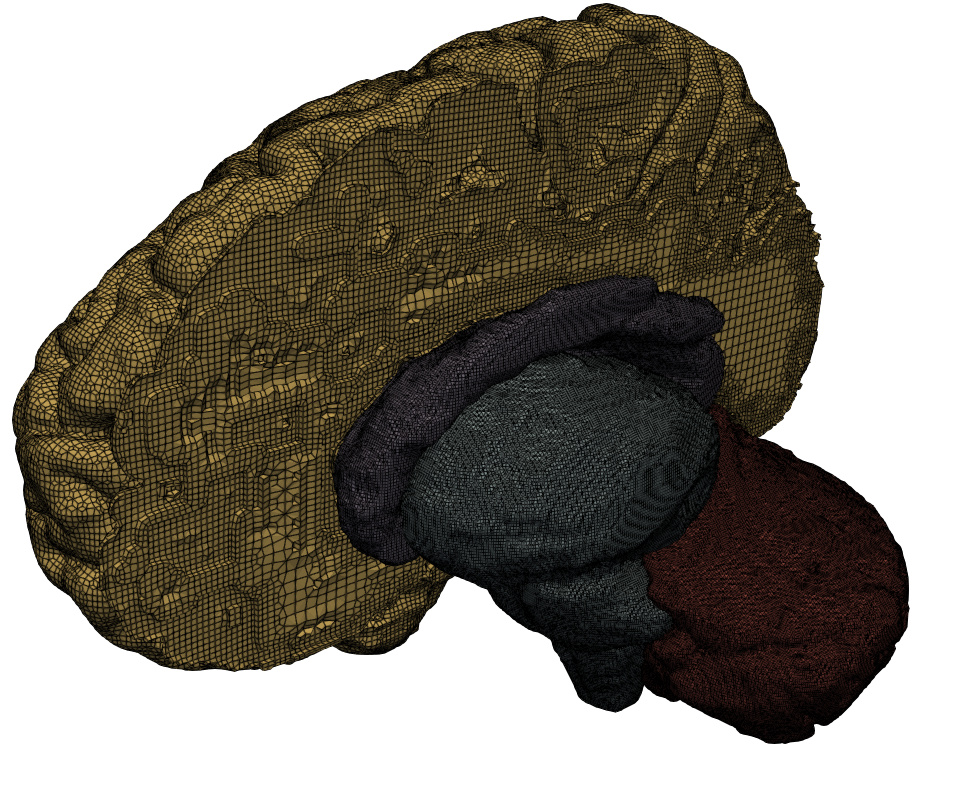
Step 9: Import into Coreform Cubit and/or ParaView
Of course, we could skip this altogether if we wanted, but you might want to bring your model back into Coreform Cubit so that you can further assemble your simulation model.
We can also import the mesh into ParaView for high-quality rendering
Appendix: Iterating
I often find that I’ll iterate quite a bit throughout this process. I’ll try building meshes, trying to have no inverted elements (scaled Jacobian < 0). Sometimes this is as simple as getting the correct Sculpt parameters (use a finer mesh, increasing smoothing iterations, turning on/off pillowing, turning on/off adaptivity, switching the adaptivity algorithm, etc). However, if you can’t seem to get a valid mesh, you can always use the --remove_bad option to delete bad elements or this often signals that there’s something wrong with your input STL file. Try going back to Step 1 and look for sliver shells, intersecting triangles, or similar issues to fix.