Trelis 17.1
Ubuntu 20.04
Issue
Is there a way to smooth or correct the imperfections generated after imprinting curves on a spherical ACIS surface? I’m attaching an example journal file. Thank you
What can we help with?
imprint_curves_on_sphere.jou (2.2 KB)
Welcome @GreekMesh!
Note: Before you set your graphics tolerance to a finer level, read the last section of this post.
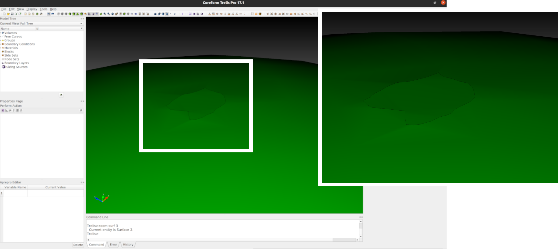
The issue you’re seeing appears to simply be a rendering issue. For example, I’ll show the render facets using the command:
graphics mode facet
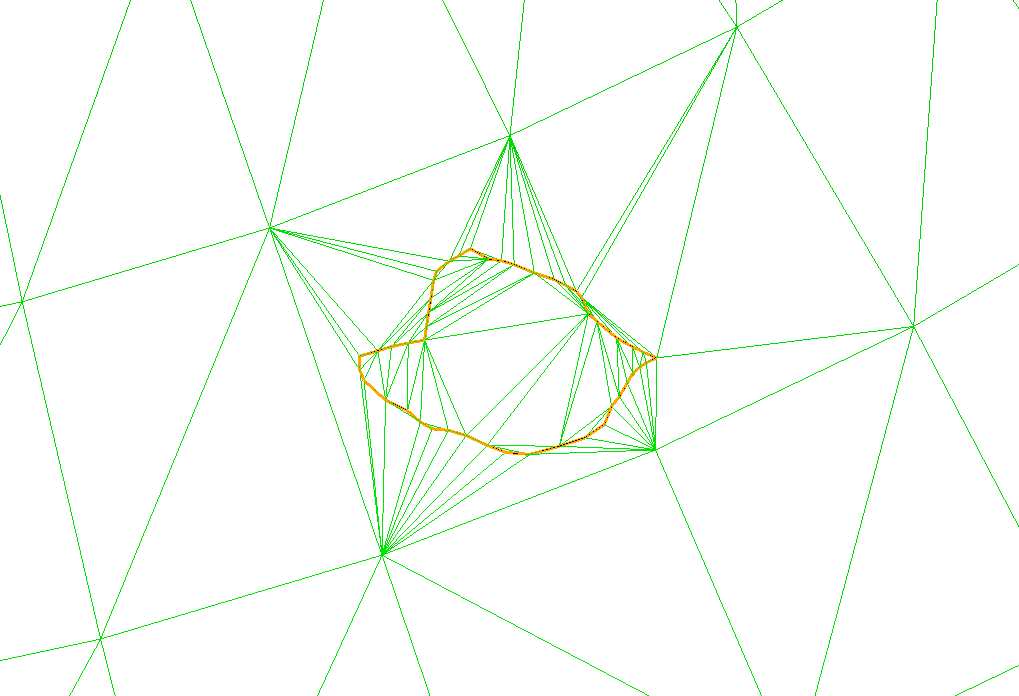
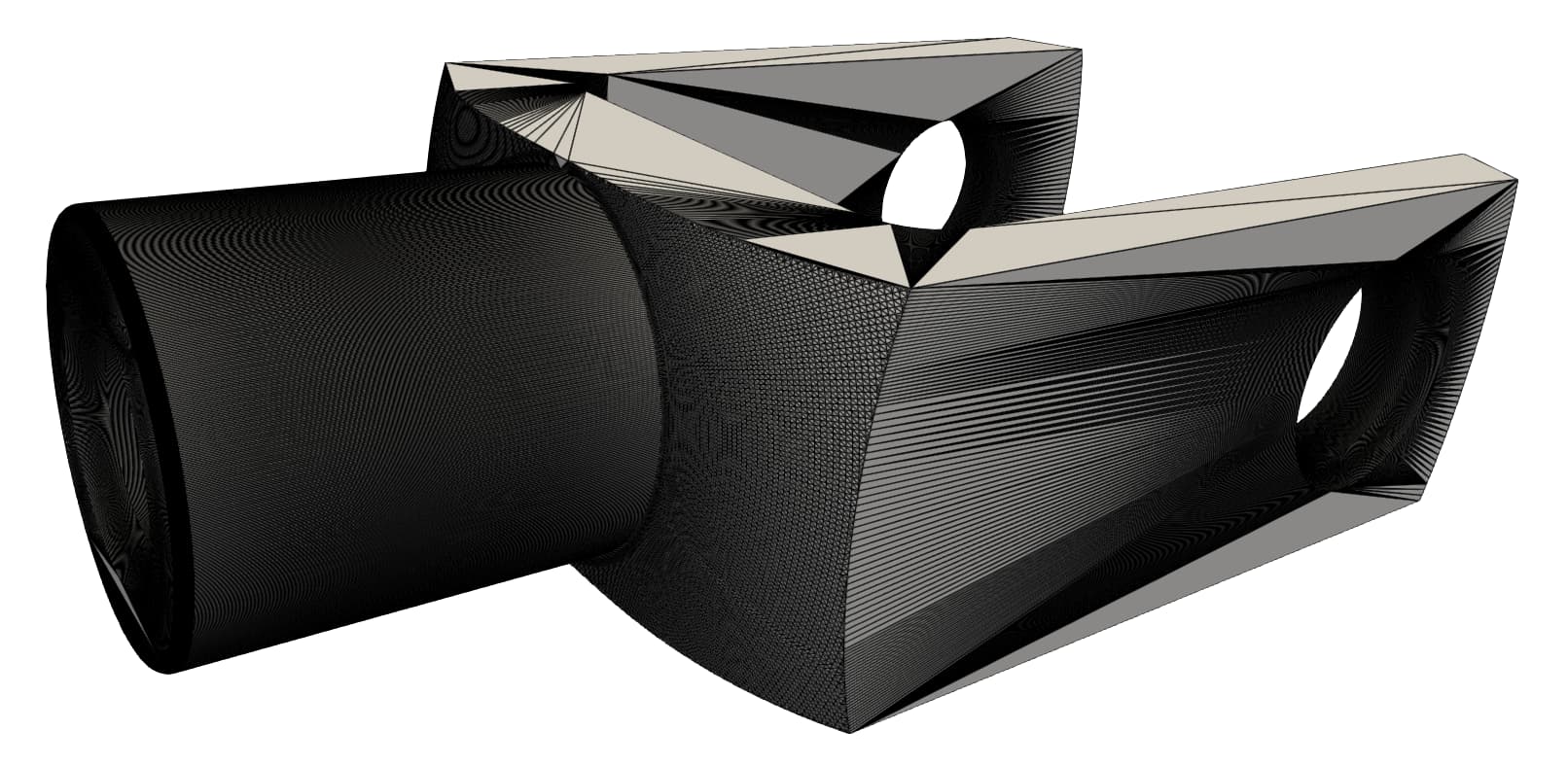
The “factory default” graphics tolerance is 15 degrees:
As you can see, there are some large facets that neighbor some very high aspect-ratio triangles. This is efficient for rendering, but can lead to the visual discrepancies you’re seeing.
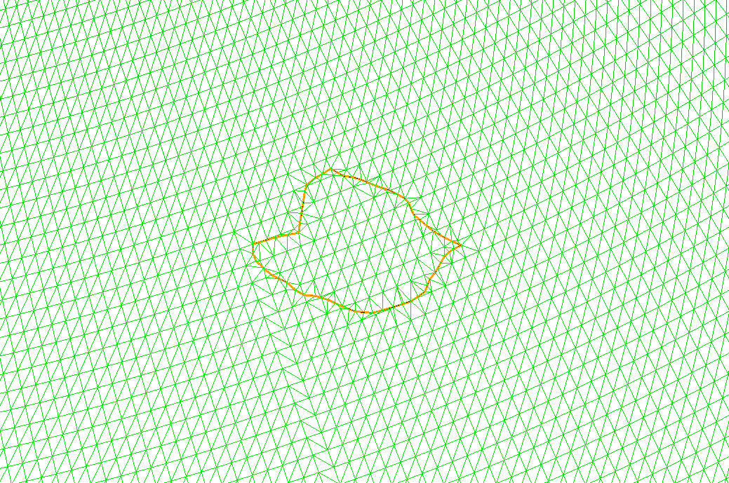
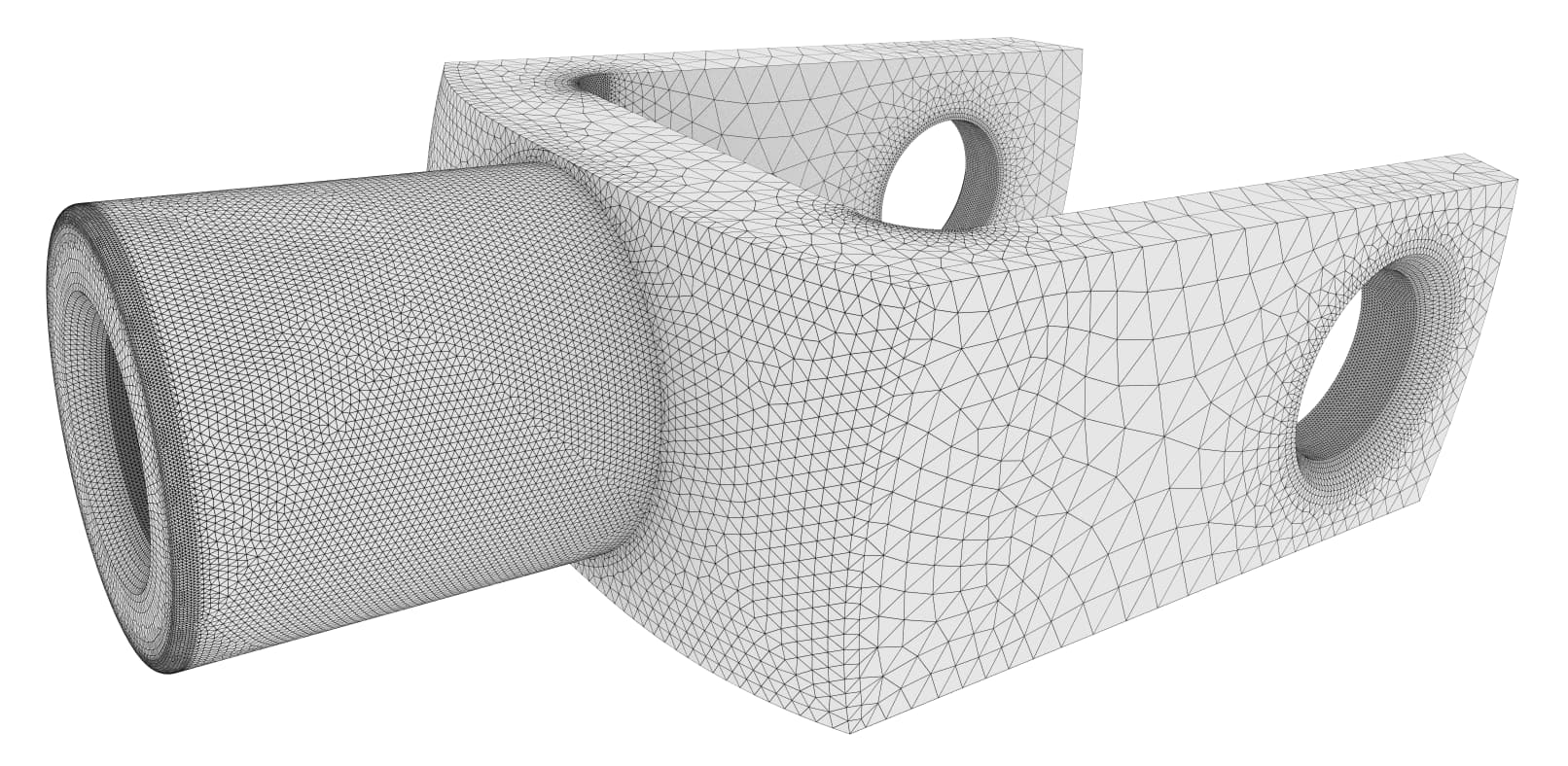
If we change the graphics tolerance to an angle of 1 degree we’ll notice that the variance in triangle size/shape is much smaller:
graphics tolerance angle 1
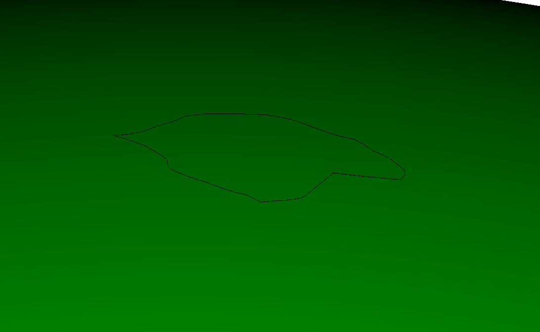
And if we set our graphics mode to back shaded:
graphics mode SmoothShade
you’ll notice that the visual discrepancies are gone:
README
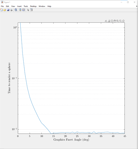
So why don’t we have the factory default render tolerance finer than 15 degrees? From a previous post I made, once you set a graphics tolerance angle smaller than 15 degrees you’ll start to notice deteriorating performance:
So what I’ll often do in my scripts is initialize them with a render tolerance of 15 degrees, then when I want to work interactively, I’ll set the angle finer. So to modify your script, I would do:
reset
graphics tolerance angle 15  ## Maximize performance
######################## Create Vertices ############################
create vertex    x 70.76 y 40.41 z 57.97
create vertex    x 70.73 y 39.84 z 58.39
create vertex    x 70.69 y 39.41 z 58.74
create vertex    x 70.58 y 38.78 z 59.29
create vertex    x 70.26 y 38.01 z 60.16
create vertex    x 70.1 y 37.67 z 60.56
create vertex    x 69.86 y 37.55 z 60.9
create vertex    x 69.63 y 37.46 z 61.23
create vertex    x 69.48 y 37.26 z 61.52
create vertex    x 69.39 y 36.82 z 61.88
create vertex    x 69.31 y 36.35 z 62.25
create vertex    x 69.28 y 35.51 z 62.76
create vertex    x 69.19 y 34.66 z 63.34
create vertex    x 69.17 y 34.12 z 63.65
create vertex    x 69.23 y 33.56 z 63.89
create vertex    x 69.03 y 32.8 z 64.49
create vertex    x 69.37 y 32.25 z 64.4
create vertex    x 69.62 y 31.81 z 64.35
create vertex    x 70.06 y 31.2 z 64.17
create vertex    x 70.38 y 31.02 z 63.9
create vertex    x 71 y 30.82 z 63.32
create vertex    x 71.48 y 30.65 z 62.86
create vertex    x 71.96 y 30.48 z 62.39
create vertex    x 72.41 y 30.33 z 61.94
create vertex    x 72.62 y 29.58 z 62.05
create vertex    x 72.85 y 28.82 z 62.14
create vertex    x 73.08 y 28.19 z 62.17
create vertex    x 73.36 y 27.34 z 62.21
create vertex    x 73.8 y 27.27 z 61.72
create vertex    x 74.1 y 27.41 z 61.3
create vertex    x 74.58 y 28.27 z 60.32
create vertex    x 74.76 y 29.19 z 59.66
create vertex    x 75.01 y 29.7 z 59.08
create vertex    x 75.13 y 30.19 z 58.68
create vertex    x 75.05 y 30.9 z 58.41
create vertex    x 75.07 y 31.66 z 57.98
create vertex    x 75.19 y 32.53 z 57.34
create vertex    x 75.25 y 33.3 z 56.83
create vertex    x 75.08 y 34.36 z 56.41
create vertex    x 74.56 y 35.69 z 56.28
create vertex    x 74.04 y 36.86 z 56.21
create vertex    x 73.43 y 37.78 z 56.4
create vertex    x 72.8 y 38.19 z 56.94
create vertex    x 72.41 y 38.58 z 57.17
create vertex    x 71.89 y 39 z 57.54
create vertex    x 71.52 y 39.29 z 57.8
create vertex    x 71.26 y 39.62 z 57.9
create vertex    x 71.03 y 39.93 z 57.96
######################## Create Polyline-Create Sphere-Imprint Curve on Spherical Surface ############################
create curve polyline vertex all
create curve vertex 48 1
create sphere radius 100
imprint surface 1  with curve all
zoom surf 3

graphics tolerance angle 1  ## Maximize quality
Hi Greg,
and thank you for your fast and clear explanation. You are 100% correct. I have see this in the past but somehow fooled me because I was exporting and visualizing an stl file.
The tricky part is that if you export the low resolution one as stl, you will “inherit” the low tolerance graphics in your facet mesh.
Thank you again
Since you mention exporting an STL file, you might be interested in a few options:
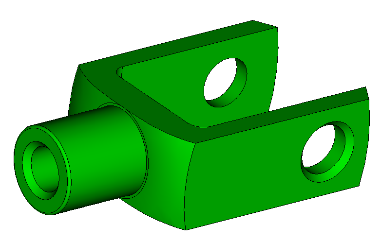
Original CAD
Specify graphics facet angle on export
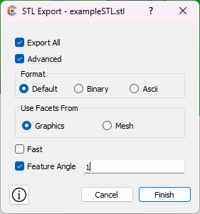
export stl binary "FineGraphicsFacets.stl" angle 1 fast overwrite
Export mesh facets
I found this option to be very beneficial in my previous career, working tangentially with additive manufacturing process engineers. The triangles resulting from a tri/tet mesh improved the robustness of many of our downstream processes in additive manufacturing.
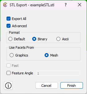
surface 1 scheme trimesh geometry approximation angle 1
mesh surface all
export stl binary "C:/Users/Owner/Desktop/MeshFacets.stl" mesh overwrite
Hi Greg,
really cool and very useful command!
Yes, 3D printing!
Thank you again.
1 Like
I think I need to ask questions here more often!
1 Like