Overview:
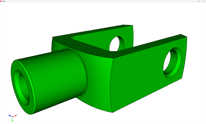
In this tutorial, we present an approach to hex-meshing the knuckle geometry included in our Coreform Training dataset (specifically, examples_only.zip) – for your convenience, I’ve included a direct download below.
CAD Geometry: knuckle.sat (161.7 KB)
Tip:
Did you know you can create a separate render window using the graphics window create <id> command? I often use this to help me create high-quality images for documentation. In the hardcopy command, used to create screenshots directly, you can reference the new window’s <id>.
Hex Meshing
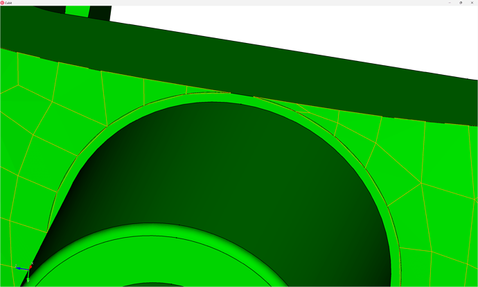
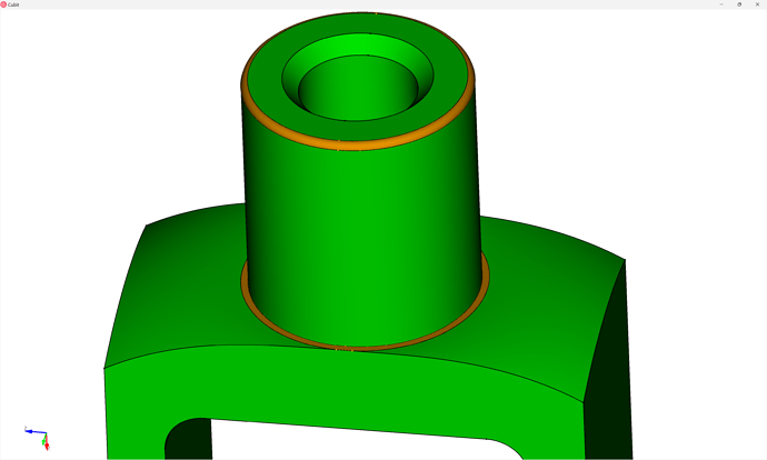
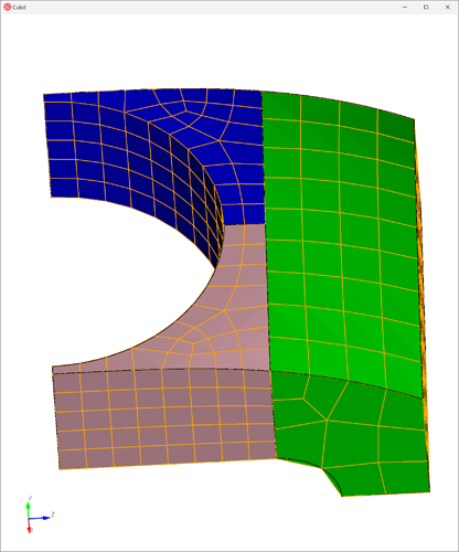
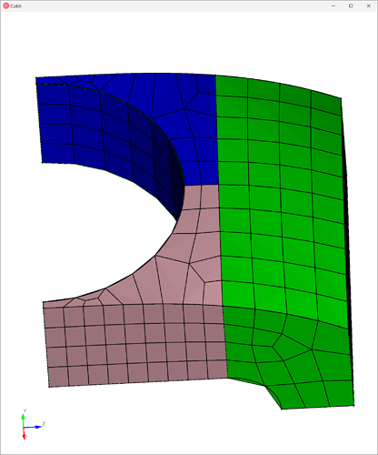
One thing to note about this geometry is that there is a small flat surface around the cylinder that intersects with the boundary in an “almost-tangent” manner. Any hex mesh on this region is going to result in pretty poor element quality - as demonstrated in the quadrilateral surface mesh in the image below. We could potentially use a “pave and sweep” hex mesh approach, allowing triangles on the surface which would be swept into wedge elements so you’d want to make sure your solver supports wedge elements before using this method. Also, your physics might dictate a quadratic (second-order) wedge element which would result in a quadratic hex mesh in order to conform to the quadratic wedge.
Instead, it might be preferable to simply defeature this small surface - either by remove surface or composite create surface commands. In this demo, we will use the former.
Import and assign sets
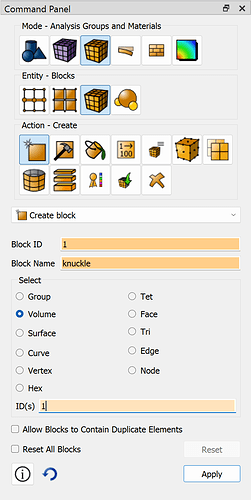
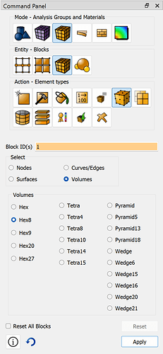
Beginning, then, we import the CAD model, assign our sets (here just a single block, but we could also perform sideset and nodeset assignments for load & boundary conditions).
reset
import acis "/path/to/knuckle.sat" nofreesurfaces heal attributes_on  separate_bodies

block 1 vol 1
block 1 name "knuckle"
block 1 element type hex8
Defeaturing
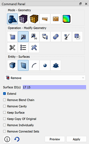
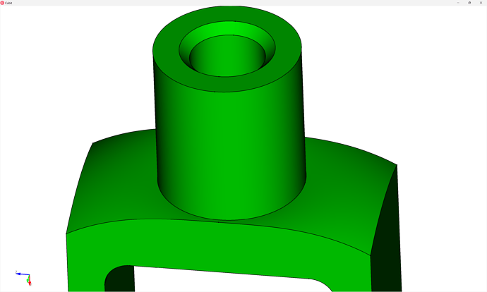
We then remove the small surface, as well as the small fillet on the top of the knuckle by extending their neighboring surfaces:
remove surface 17  extend
remove surface 15  extend
Partitioning for meshability
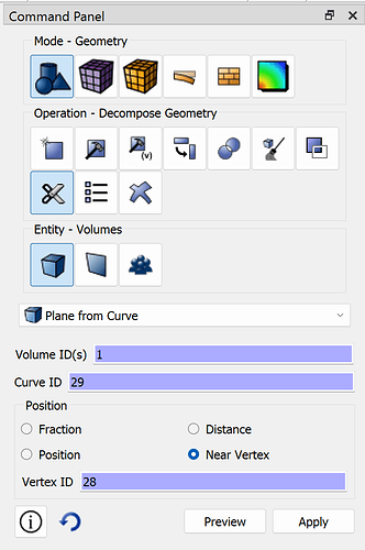
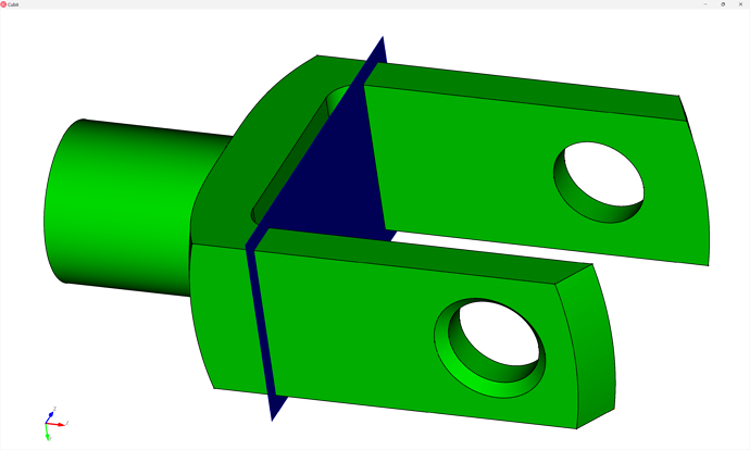
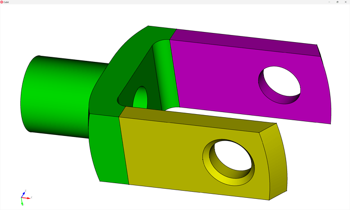
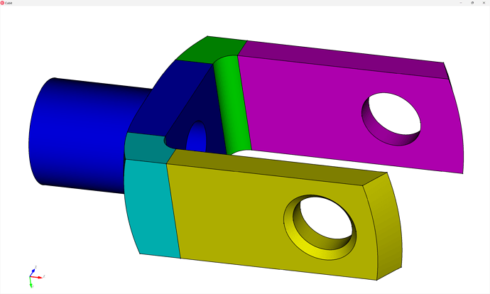
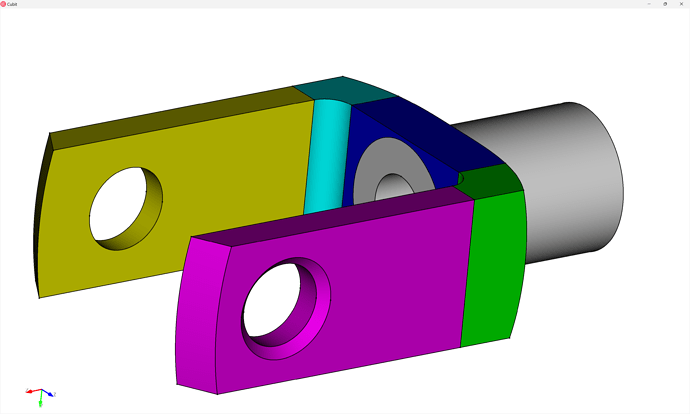
First we “webcut” the legs to separate them from the body
webcut volume 1 with plane normal to curve 29 close_to vertex 28
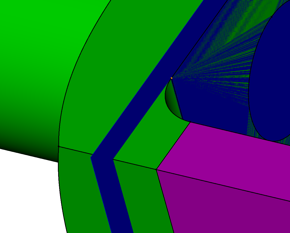
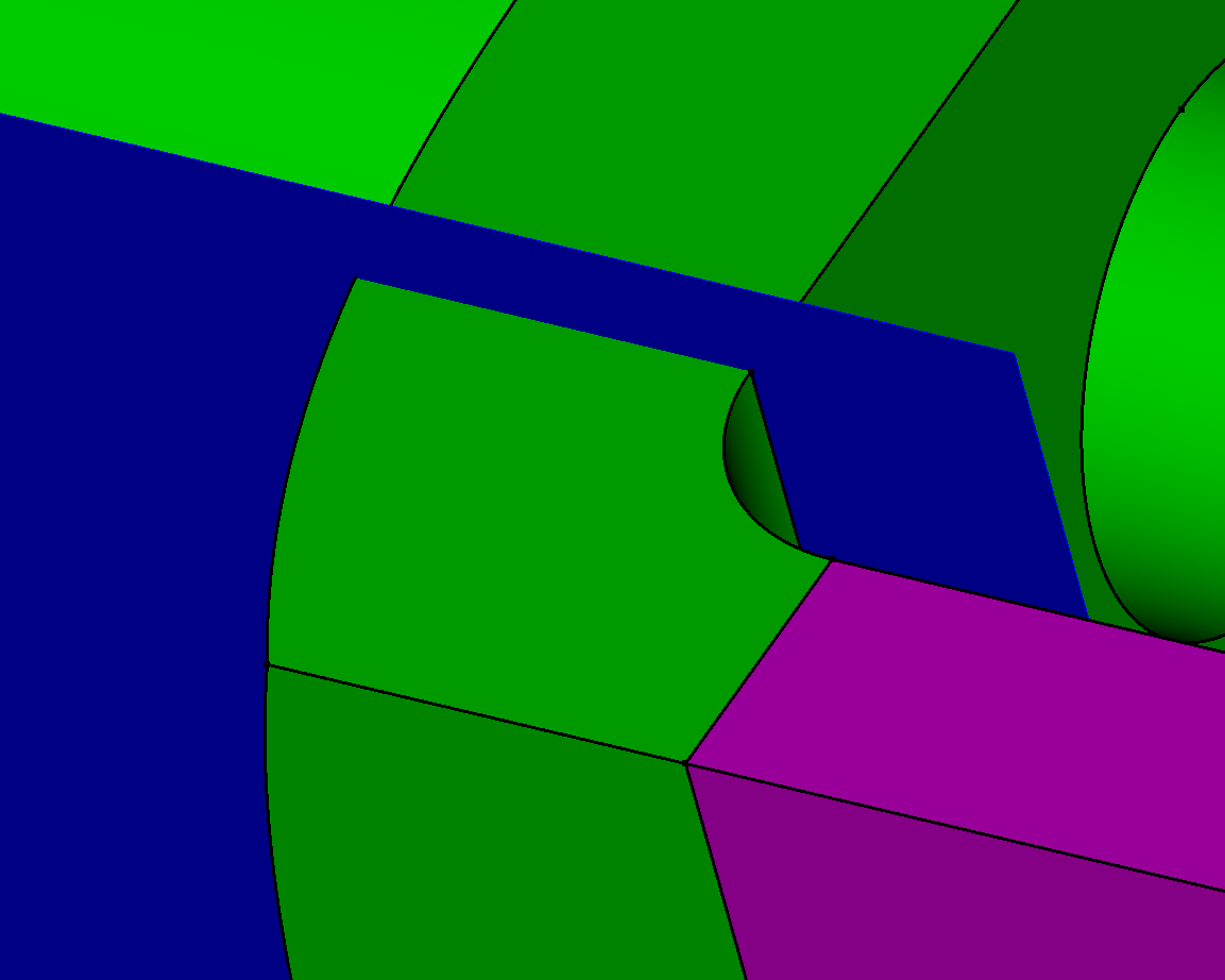
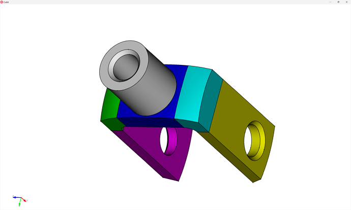
Next we’ll webcut the two shoulders – note that whenever we perform a webcut we want to try to create “as close to 90-degree” cuts as possible - rather than a tangency.
For example: DON’T DO THIS
DO THIS
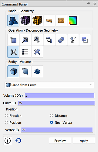
webcut volume 1  with plane normal to curve 35  close_to vertex 29
webcut volume 1  with plane normal to curve 35  close_to vertex 32
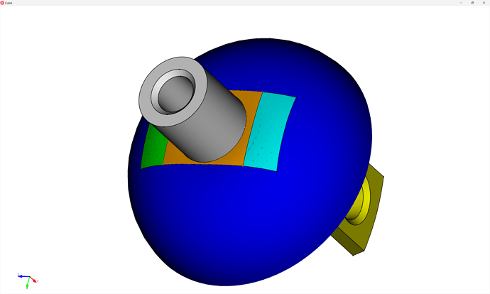
Next, we’ll use the cylindrical surface to define a cut through the top region of the knuckle, by extending it:
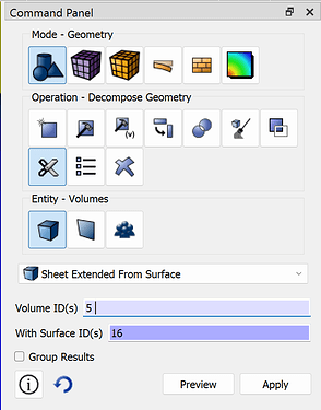
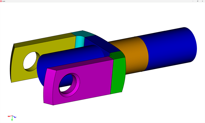
webcut volume 5 with sheet extended from surface 16
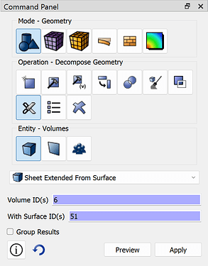
Then we’ll use a same webcut operation to separate the cylinder region from its base:
webcut volume 6 with sheet extended from surface 51
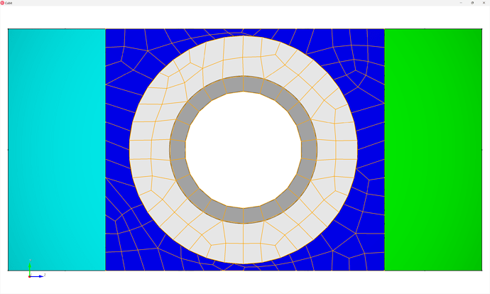
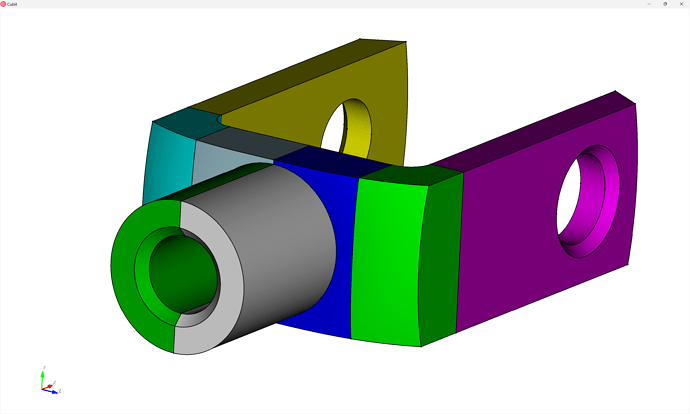
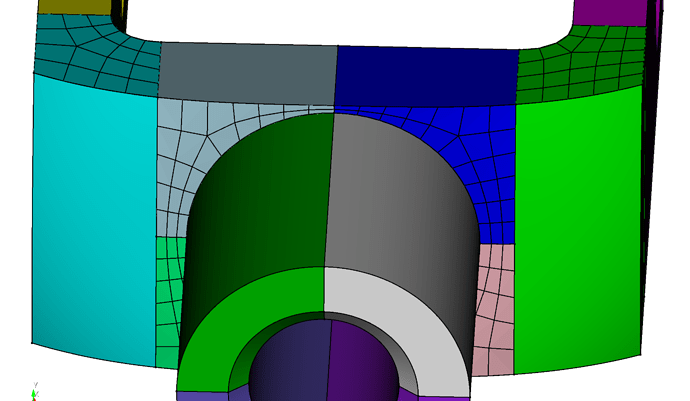
While the geometry is technically meshable in this state, actually it has been since separating the shoulders, I’m going to partition the “head and shoulder” region to help the automatic meshing algorithms generate a higher-quality mesh. For example, here is the quad mesh that it would currently generate – note that I would expect a structured mesh on the annulus regions (I could specify the hole mesh scheme to do this) and the thin regions in the base have relatively-poor quality elements:
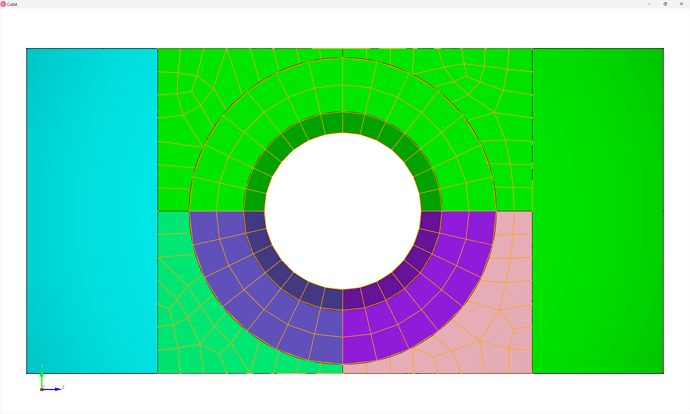
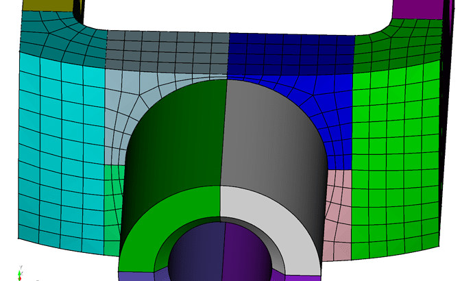
Whereas, after cutting we can get a mesh that looks like:
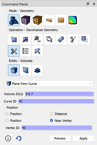
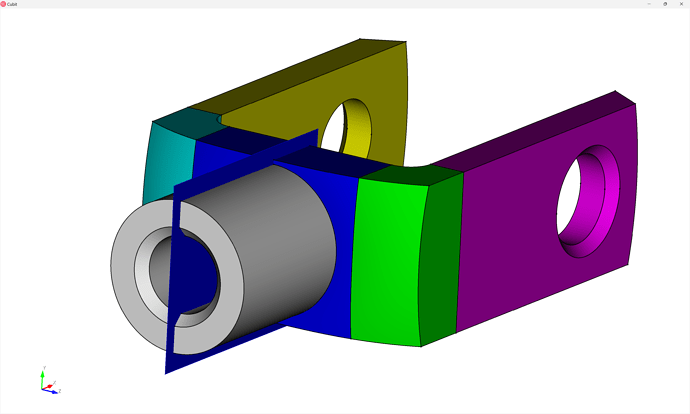
webcut volume all with plane normal to curve 43 close_to vertex 40
and finally:
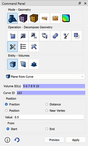
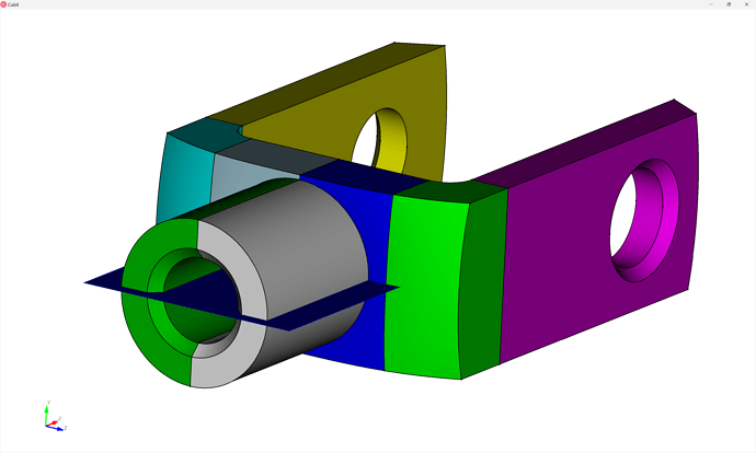
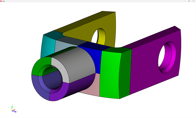
webcut volume all with plane normal to curve 163 fraction .5 from start
Post-partitioning cleanup
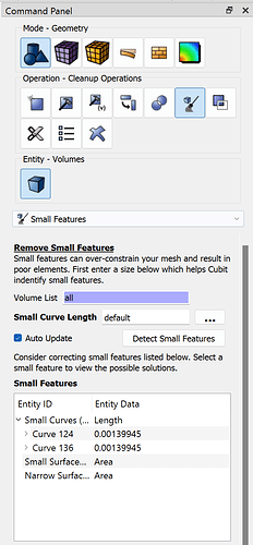
During the webcutting procedure we sometimes might create small entities due to inexactness in the CAD or unaligned CAD entities. So it’s good to check for small features using the Cleanup Operations - Small Features command panel:
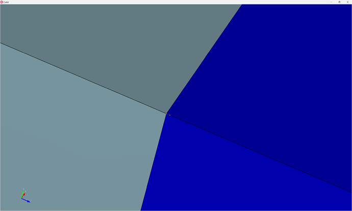
By clicking on each of the two Small Curves we can see that these two curves were caused by a webcut barely missing a vertex, and can safely be ignored:
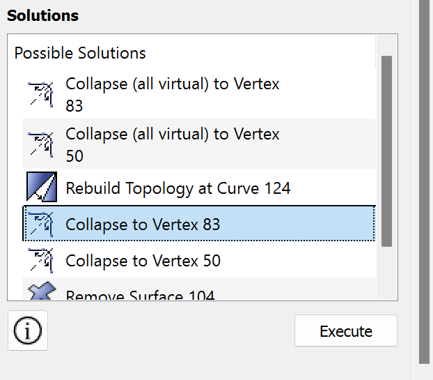
The same command panel suggests some solutions - you can explore each solution to see which one works best. It’s almost always prefereable to perform real geometry operations rather than virtual geometry operations, so I’m using the Collapse to Vertex 83 solution rather than the Collapse (all virtual) to Vertex 83 command:
TIP:
If you’re writing a journal file, try each of the options and then try to mesh the resulting volue to check meshability & quality. If it doesn’t work you can replay your journal file up to this point and try a different solution. Or turn undo on to simply undo the attempted solution.
Enforce contiguous mesh
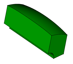
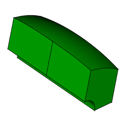
By convention, webcuts in Cubit result in disconnected regions, meaning that meshes will not share element boundaries (e.g., nodes) across their boundaries:
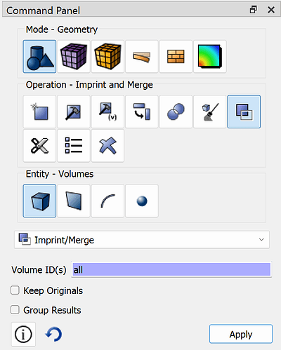
So what we need to do is imprint and merge the volumes together. The imprint operation projects CAD topology onto nearby entities:
While merge will identify shareable surfaces and enforce continuity:
Because we often use Coreform Cubit to mesh single parts at a time, many users will often use imprint and merge all entities - though when working with assemblies a bit more care is needed.
imprint all
merge all
Meshing
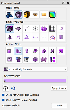
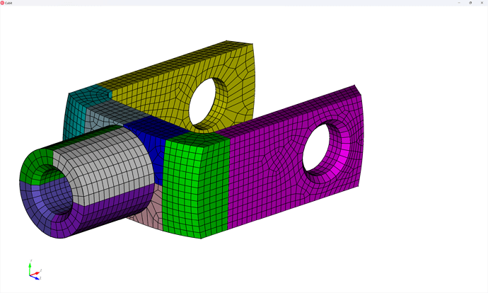
We can let Coreform Cubit automatically assign mesh schemes and generate the mesh:
mesh volume all
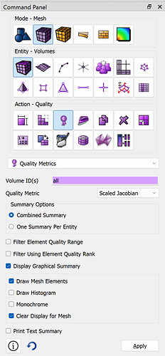
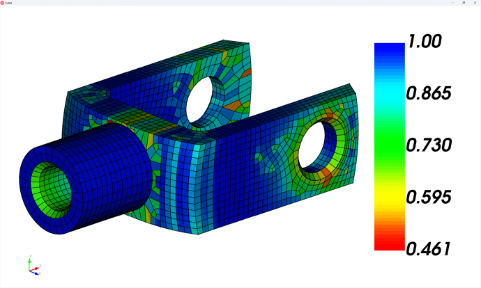
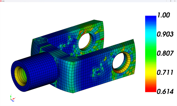
Looking at the quality (I like the Scaled Jacobian metric) there may be a few areas we can improve the quality if we manually specify the schemes.
quality volume all scaled jacobian global draw mesh
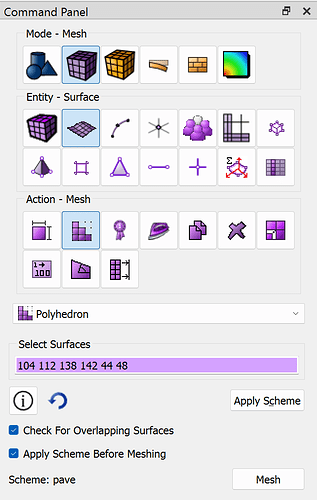
There are several five-sided surfaces (think “square with one corner trimmed off”) that the polyhedron surface mesh-scheme generally works pretty well… we’ll specify polyhedron schemes and then set a “sweep” volume mesh scheme.
surface 104 112 138 142 44 48 scheme polyhedron
mesh surface 104 112 138 142 44 48
volume 1  redistribute nodes off
volume 1  scheme Sweep  source surface 48    target surface 47   sweep transform least squares
volume 1  autosmooth target on  fixed imprints off  smart smooth off
mesh volume 1
volume 4  redistribute nodes off
volume 4  scheme Sweep  source surface 44    target surface 45   sweep transform least squares
volume 4  autosmooth target on  fixed imprints off  smart smooth off
mesh volume 4
volume 8  redistribute nodes off
volume 8  scheme Sweep  source surface 138    target surface 161   sweep transform least squares
volume 8  autosmooth target on  fixed imprints off  smart smooth off
mesh volume 8
volume 5  redistribute nodes off
volume 5  scheme Sweep  source surface 104    target surface 106   sweep transform least squares
volume 5  autosmooth target on  fixed imprints off  smart smooth off
mesh volume 5
volume 11  redistribute nodes off
volume 11  scheme Sweep  source surface 112    target surface 110   sweep transform least squares
volume 11  autosmooth target on  fixed imprints off  smart smooth off
mesh volume 11
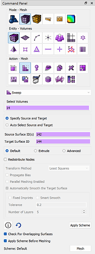
volume 14  redistribute nodes off
volume 14  scheme Sweep  source surface 142    target surface 144   sweep transform least squares
volume 14  autosmooth target on  fixed imprints off  smart smooth off
mesh volume 14
TIP:
To minimize number of lines in my scripts, I’ll often compress some of the repeated commands into single commands:
volume 1 4 8 5 11 14  redistribute nodes off
volume 1 4 8 5 11 14   autosmooth target on  fixed imprints off  smart smooth off
volume 1  scheme Sweep  source surface 48    target surface 47   sweep transform least squares
volume 4  scheme Sweep  source surface 44    target surface 45   sweep transform least squares
volume 8  scheme Sweep  source surface 138   target surface 161  sweep transform least squares
volume 5  scheme Sweep  source surface 104   target surface 106  sweep transform least squares
volume 11 scheme Sweep  source surface 112   target surface 110  sweep transform least squares
volume 14 scheme Sweep  source surface 142   target surface 144  sweep transform least squares
mesh volume 1 4 8 5 11 14
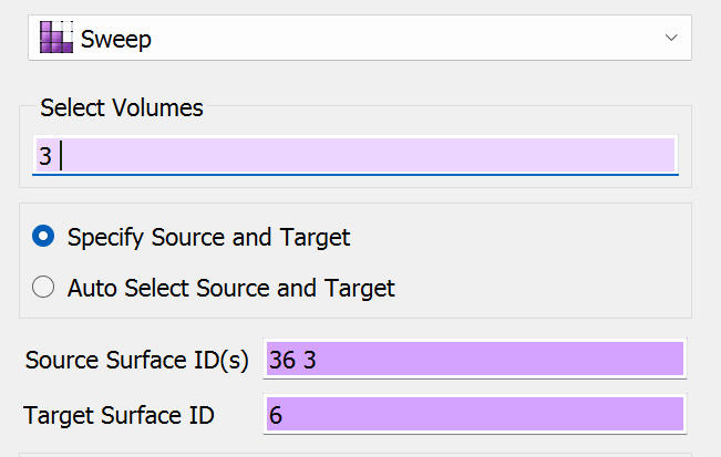
Then we can define a “many-to-one sweep on the two legs”, which is done by choosing the sweep scheme and entering multiple source surfaces:
volume 2 3  redistribute nodes off
volume 2 3   autosmooth target on  fixed imprints off  smart smooth off
volume 2  scheme Sweep  source surface 33 7    target surface 9   sweep transform least squares
volume 3  scheme Sweep  source surface 36 3    target surface 6   sweep transform least squares
mesh volume 2 3
Looking at the quality again, note that we’ve improved the worst quality elements by ~50%
Complete journal file
(With some additional comments / cleanup)
reset
import acis "path/to/knuckle.sat" nofreesurfaces heal attributes_on  separate_bodies

## Assign sets
block 1 vol 1
block 1 name "knuckle"
block 1 element type hex8

## Defeature
remove surface 17  extend
remove surface 15  extend

## Partion for meshing
webcut volume 1  with plane normal to curve 29  close_to vertex 28
webcut volume 1  with plane normal to curve 35  close_to vertex 29
webcut volume 1  with plane normal to curve 35  close_to vertex 32
webcut volume 5  with sheet extended from surface 16
webcut volume 6  with sheet extended from surface 51
webcut volume 5 6 7 with plane normal to curve 43  close_to vertex 40
webcut volume 5 6 7 8 9 10 with plane normal to curve 163  fraction .5 from start

## Cleanup small curves
collapse curve 124 vertex 83 real_split
collapse curve 136 vertex 95 real_split

## Enforce contiguous mesh
imprint all
merge all

## Generate Mesh
surface 104 112 138 142 44 48 scheme polyhedron
mesh surface 104 112 138 142 44 48

volume 1 2 3 4 8 5 11 14  redistribute nodes off
volume 1 2 3 4 8 5 11 14   autosmooth target on  fixed imprints off  smart smooth off
volume 1  scheme Sweep  source surface 48    target surface 47   sweep transform least squares
volume 4  scheme Sweep  source surface 44    target surface 45   sweep transform least squares
volume 8  scheme Sweep  source surface 138   target surface 161  sweep transform least squares
volume 5  scheme Sweep  source surface 104   target surface 106  sweep transform least squares
volume 11 scheme Sweep  source surface 112   target surface 110  sweep transform least squares
volume 14 scheme Sweep  source surface 142   target surface 144  sweep transform least squares
volume 3  scheme Sweep  source surface 36 3    target surface 6   sweep transform least squares
volume 2  scheme Sweep  source surface 33 7    target surface 9   sweep transform least squares

mesh volume all
