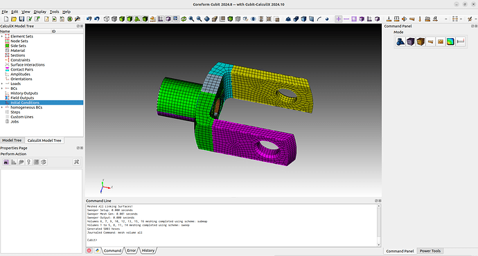
This example is a extension from the meshing tutorial for the knuckle that @gvernon did. You will need the free open source component Cubit-CalculiX for Cubit to do this example.
The whole example can be found on Github: Example Knuckle
We will first get the geometry from the forum and run the journal to have our starting point.
#!cubit
reset
import acis "path/to/knuckle.sat" nofreesurfaces heal attributes_on  separate_bodies
## Assign sets
block 1 vol 1
block 1 name "knuckle"
block 1 element type hex8
## Defeature
remove surface 17  extend
remove surface 15  extend
## Partion for meshing
webcut volume 1  with plane normal to curve 29  close_to vertex 28
webcut volume 1  with plane normal to curve 35  close_to vertex 29
webcut volume 1  with plane normal to curve 35  close_to vertex 32
webcut volume 5  with sheet extended from surface 16
webcut volume 6  with sheet extended from surface 51
webcut volume 5 6 7 with plane normal to curve 43  close_to vertex 40
webcut volume 5 6 7 8 9 10 with plane normal to curve 163  fraction .5 from start
## Cleanup small curves
collapse curve 124 vertex 83 real_split
collapse curve 136 vertex 95 real_split
## Enforce contiguous mesh
imprint all
merge all
## Generate Mesh
surface 104 112 138 142 44 48 scheme polyhedron
mesh surface 104 112 138 142 44 48
volume 1 2 3 4 8 5 11 14  redistribute nodes off
volume 1 2 3 4 8 5 11 14   autosmooth target on  fixed imprints off  smart smooth off
volume 1  scheme Sweep  source surface 48    target surface 47   sweep transform least squares
volume 4  scheme Sweep  source surface 44    target surface 45   sweep transform least squares
volume 8  scheme Sweep  source surface 138   target surface 136  sweep transform least squares
volume 5  scheme Sweep  source surface 104   target surface 106  sweep transform least squares
volume 11 scheme Sweep  source surface 112   target surface 110  sweep transform least squares
volume 14 scheme Sweep  source surface 142   target surface 144  sweep transform least squares
volume 3  scheme Sweep  source surface 36 3    target surface 6   sweep transform least squares
volume 2  scheme Sweep  source surface 33 7    target surface 9   sweep transform least squares
mesh volume all
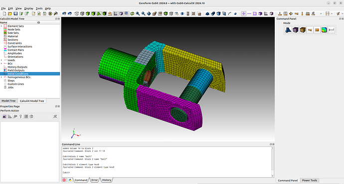
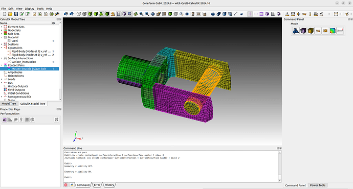
Now we can start with adding a bolt. We will first create a cylinder and cut him in the middle. This way we can get a surface for a rigid body constraint. After the cut we merge the cylinder volumes and move them to holes from the knuckle. Then we will mesh the bolt and assign the block and element type.
# create bolt
create Cylinder height 36 radius 5
webcut volume 17  with plane zplane offset 0
merge vol 17 18
move Surface 174  location vertex 33  except x y include_merged
move Surface 175  location surface 2  except z include_merged
mesh vol 17 18
block 2 vol 17 18
block 2 name "bolt"
block 2 element type hex8
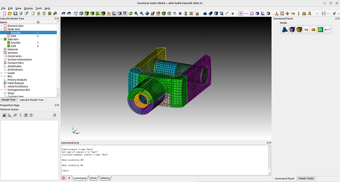
Next we can already create the nodesets and sidesets that will be used for our boundary conditions, constraints and contact definitions.
#nodesets
nodeset 1 add node all in surface 115 123 149 152 with x_coord < -18
nodeset 1 name "knuckle"
nodeset 2 add surface 174
nodeset 2 name "bolt"
#sidesets
sideset 1 add surface 2 8
sideset 1 name "knuckle"
sideset 2 add surface 177 175
sideset 2 name "bolt"
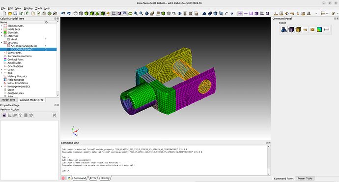
We define the Material and assign it to the Sections.
#material
create material "steel" property_group "CalculiX-FEA"
modify material "steel" scalar_properties "CCX_ELASTIC_USE_CARD" 1
modify material "steel" scalar_properties "CCX_ELASTIC_ISO_USE_CARD" 1
modify material "steel" matrix_property "CCX_ELASTIC_ISO_MODULUS_VS_POISSON_VS_TEMPERATURE" 210000 0.3 0
modify material "steel" scalar_properties "CCX_PLASTIC_ISO_USE_CARD" 1
modify material "steel" scalar_properties "CCX_EXPANSION_ISO_USE_CARD" 1
modify material "steel" scalar_properties "CCX_CONDUCTIVITY_ISO_USE_CARD" 1
modify material "steel" scalar_properties "CCX_PLASTIC_USE_CARD" 1
modify material "steel" matrix_property "CCX_PLASTIC_ISO_YIELD_STRESS_VS_STRAIN_VS_TEMPERATURE" 235 0 0
#section assignment
ccx create section solid block all material 1
Now we will define a rigid body constraint in the middle of the bolt and also the contact between the bolt and the knuckle.
#create vertex for reference points
create vertex location center curve 265
create vertex location center curve 265
create vertex location on surface 174  center
create vertex location on surface 174  center
mesh vertex all
#constraints
ccx create constraint rigid body nodeset 1 ref 181 rot 182
ccx create constraint rigid body nodeset 2 ref 183 rot 184
#surface interaction
ccx create surfaceinteraction name "surface_interaction" linear slopeK 1e+7 sigmaINF 1 c0 1e-3
#contact pair
ccx create contactpair surfaceinteraction 1 surfacetosurface master 1 slave 2
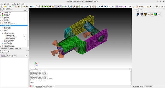
As boundary conditions we will set the displacements from the knuckle nodeset to zero. The reference point for the bolt will get a displacement set for moving in the x-direction and all other dofs are set to zero. Note that with
ccx draw
the calculix boundary conditions can be drawn in cubit.
#bc
create displacement name "knuckle_fix" on vertex 181 182 dof all fix 0
create displacement name "bolt_translation" on vertex 183 dof all fix 0
modify displacement 2 dof 1 fix 2
create displacement name "bolt_rotation" on vertex 184 dof all fix 0
As we want some calculix results for postprocessing, we need to define some outputs.
We will define history outputs to track the forces in the bolt and the field outputs to obtain the stresses and strains.
#outputs
ccx create historyoutput name "ho_knuckle" node
ccx modify historyoutput 1 node nodeset 3
ccx modify historyoutput 1 node key_on u rf
ccx modify historyoutput 1 node key_off nt tsf ttf pn psf ptf mach cp vf depf turb mf rfl
ccx create historyoutput name "ho_bolt_translation" node
ccx modify historyoutput 2 node nodeset 4
ccx modify historyoutput 2 node key_on u rf
ccx modify historyoutput 2 node key_off nt tsf ttf pn psf ptf mach cp vf depf turb mf rfl
ccx create historyoutput name "ho_bolt_rotation" node
ccx modify historyoutput 3 node nodeset 5
ccx modify historyoutput 3 node key_on u rf
ccx modify historyoutput 3 node key_off nt tsf ttf pn psf ptf mach cp vf depf turb mf rfl
ccx create fieldoutput name "fo_node" node
ccx modify fieldoutput 1 node key_on rf u
ccx modify fieldoutput 1 node key_off cp depf dept dtf hcri keq mach maxu mf nt pnt pot prf ps psf pt ptf pu rfl sen ts tsf tt ttf turb v vf
ccx create fieldoutput name "fo_element" element
ccx modify fieldoutput 2 element key_on e s
ccx modify fieldoutput 2 element key_off ceeq ecd emfb emfe ener err her hfl hflf maxe maxs me peeq phs sf smid sneg spos svf sdv the zzs
ccx create fieldoutput name "fo_contact" contact
ccx modify fieldoutput 3 contact contact_elements_on
ccx modify fieldoutput 3 contact key_on cdis cstr cels pcon
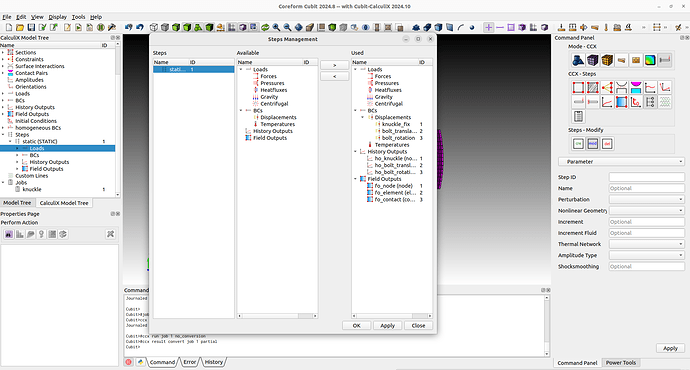
We only now need to create a step. In this case we create a static step with nonlinear geometry. As we have a contact problem here we will choose a small increment size. This way calculix should need less iterations per increment to find the convergence.
With the steps management we can easily assign the boundary conditions and outputs that should be used for the step.
The last thing to do is to create a job and run it.
#step
ccx create step name "static" static
ccx modify step 1 parameter nlgeom_yes inc 10000
ccx modify step 1 static totaltimeatstart 0 initialtimeincrement 0.02 timeperiodofstep 1 minimumtimeincrement 1e-06 maximumtimeincrement 0.02
ccx step 1 add bc displacement 1 2 3
ccx step 1 add historyoutput 1 2 3
ccx step 1 add fieldoutput 1 2 3
#job
ccx create job name "knuckle"
ccx run job 1
After the run the results will automatically be converted for paraview. You will notice that just like in the boltet connection example some contact results are skipped. Just run the conversion command with the partial option to get all results into paraview.
ccx result convert job 1 partial
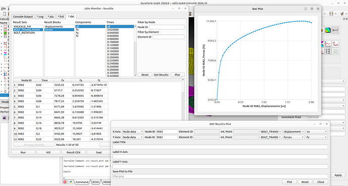
When the results are loaded into cubit we can already peak into the results using the .frd and .dat tabs in the job monitor. For example we can plot the force from the reference point of the bolt over its displacements.
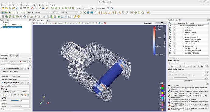
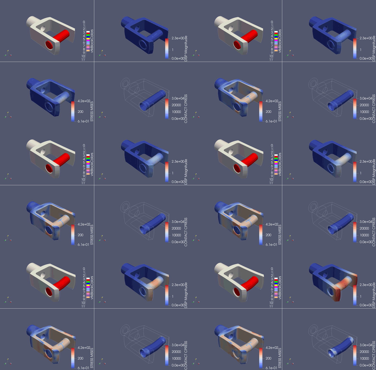
The results can be opened with paraview for the postprocessing. As we convert the results into partitioned datasets, viewing single parts or sets is also possible.
Also note that with the 2024.10 update of Cubit-CalculiX you can now save the whole model with the standard .cub5 from cubit. Everytime you save or load such files. The component will save and try to load data from the .cub5 . The loaded .frd and .dat results can be stored too in this file. So if you store the results with the whole model you just need to hit the convert button again to create the paraview files.
