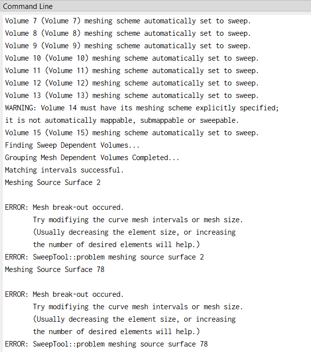
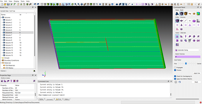
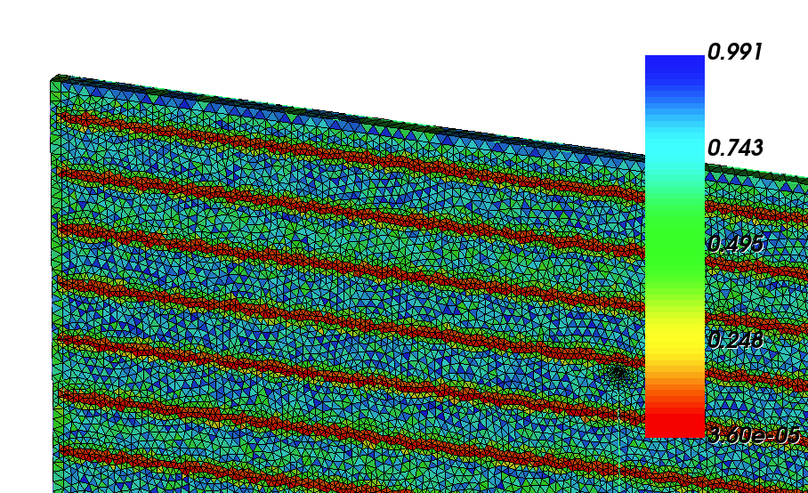
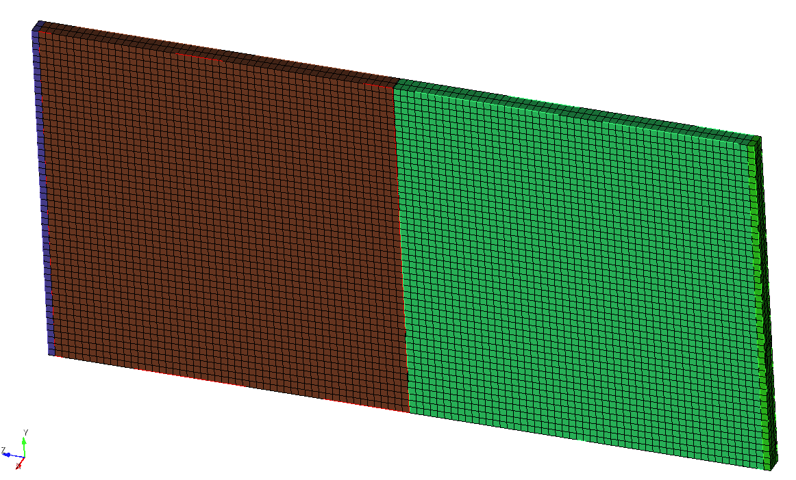
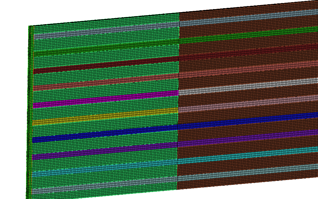
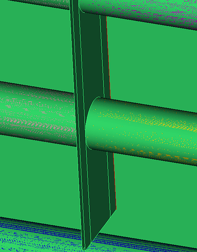
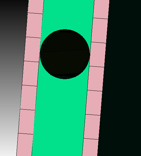
Actually my model is a fibre reinforced matrix composite containing one matrix volume, 12 fibres and 2 volume for holding and a crack at the centre. During meshing with automatic sizing tool for all ids, only fibres are meshed and matrix and holding plates are not able to meshed. Here is the screenshots I have provided. Please give me the solution for meshing the whole volume.
Hi,
could you please share the journal file, so that i can take a closer look at the problem.
Okay, i see where the break out occurs.
If you want to mesh without any further decomposition of the geometry you could already do that with a tetmesh.
reset
open "errorsample.cub5"
delete mesh
imprint vol all
merge vol all
volume all scheme tetmesh
mesh vol all
But this will lead to a really bad element quality at the tangencies.
Is it necessary that the fibres have the same thickness as the volumes? More thickness of the volumes will solve the break out issue and we don’t have to worry about the mesh quality in the tangency.
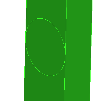
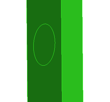
if we could allow more thickness of the volume then you would basically only need 2 webcuts at the crack to get it meshable.
reset
open "errorsample.cub5"
delete mesh

sweep surface 16 71 90  perpendicular distance 0.05
sweep surface 11 73 85  perpendicular distance 0.05

remove surface 86  extend
remove surface 88  extend
remove surface 65  extend
remove surface 67  extend
remove surface 12  extend
remove surface 14  extend
remove surface 70  extend
remove surface 72  extend

webcut volume 14 with sheet extended from surface 116
webcut volume 14 with sheet extended from surface 118

imprint vol all
merge vol all

Volume all size 0.05
volume 1 scheme sweep target surface 108
volume 15 scheme sweep target surface 122

mesh vol all
Actually the thickness of fibres are slightly smaller than thickness of matrix. If I webcut the whole volume to 2 volumes will I able to do hex mesh for whole volume with less elements?
The gap was so small that i missed it. If you have such a small gap, then we get the problems above, or you will have to set a very small mesh size for good elements quality. but this will drive the element count extremely up.
Do you mean to cut the volume in half with a plane and use the symmetry?
reset
open "errorsample.cub5"
delete mesh

sweep surface 16 71 90  perpendicular distance 0.05
sweep surface 11 73 85  perpendicular distance 0.05

remove surface 86  extend
remove surface 88  extend
remove surface 65  extend
remove surface 67  extend
remove surface 12  extend
remove surface 14  extend
remove surface 70  extend
remove surface 72  extend

webcut volume 14 with sheet extended from surface 116
webcut volume 14 with sheet extended from surface 118
webcut volume all with plane normal to curve 118  fraction 1 from end
delete volume all except 1 to 18

imprint vol all
merge vol all

Volume all size 0.05

mesh vol all
how much elements has been generated in this model? Can you send me this file in .cub5 format?
Sorry i am currently out of office. you just have to open the journal editor and copy paste the above commands and play the journal file. The ability to work with a journal file is one of the advantages of cubit. If you need more or less elements you can adjust the mesh size for the volumes in the journal file and play it again. This way you don’t have to start from the beginning again every time you want something changed.
the above mesh was around 65k elements.
It’s done sir. Thank you so much. Can you provide me any tutorial video or any user guide manual for webcut? Or please explain all these commands why you remove surface 86 extend and so on, and 3 webcuts and imprint, merge. It will be helpful for me in further meshing.
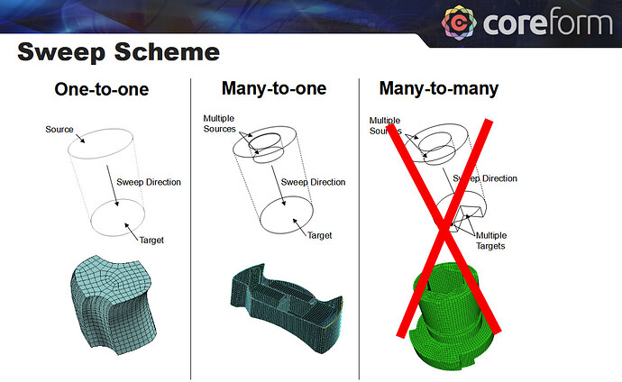
the webcuts were done to get sweepable volumes. To sweep a volume you can have multiple source surfaces but only one target surface.
if cubit doesn’t automatically choose the right source and target surfaces you have to set them manually. if the geometry is well prepared there is often no need to set them manually.
the surfaces were removed to get a whole surface where the fibres are connected. Otherwise we would still have to face the issues from above.
With imprint we achieve a connected topology between the surfaces. The merge is done to really connect the volumes and get a mesh without coincident nodes.
There is a lot of learning material in the cubit documentation. I really like the training material. Its a lot of content and takes its time, but its totally worth it.
In coreform cubit I know the surface id, How can I know that this surface id belongs to which surface? What is the command for this?
And one small doubt, after importing to .g file if I want to change my nodelist or block then it is showing error like if I run that file in a modelling software It is not showing that same nodelist. Suppose for example- I have assigned some nodes to nodelist ID 1, then if I change the nodes with same ID 1 it is showing nodelist ID 1 doesn’t exist. How can I fix it?
You can look the surface ids up in the property widget, thats normally found on the left side at the bottom in the gui.
Another apporach is, if you have selected entities in the gui, than you can type “e” to get the selection in the command line window.
If you want labels for the surfaces, then use
label surface on
Adding specific nodes usually works like this
reset
create brick x 1
mesh vol 1
nodeset 1 add node 570
nodeset 1 add node 572
nodeset 1 add node 573
nodeset 1 add node 576
Could you share the journal file, so i can see whats going on?
And if I want to remove that node from that particular nodeset what should I write?
Actually, my model is a fiber reinforced matrix composite containing one matrix volume, 12 fibers and 2 volume (fiber matrix composite structure) and a crack at the center. During meshing with automatic sizing tool for all ids, only fibers are meshed and matrix and holding plates are not able to be meshed. Here is the .cub5 file I have provided. Please give me the solution for meshing the whole volume.
cubit01error2.cub5 (1.8 MB)
you still have some uncleaned surfaces. for example volume 36
currently the same issues from above are preventing the geometry from getting meshed.
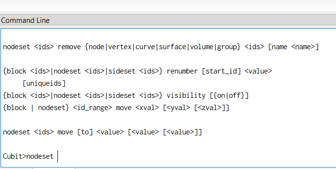
about removing entities from the nodeset
the command syntax is
nodeset <ids> remove {node|vertex|curve|surface|volume|group} <ids> [name <name>]
you can look up command syntaxes for example with
nodeset ?
in the command line window. on hitting the ? the command syntax will be shown
Can you please help me by writing the journal file and fix the meshing problem?
cubit01error2.cub5 (1.8 MB)
reset
open "cubit01error2.cub5"
delete mesh
unmerge volume all
remove surface 33 extend
remove surface 136  extend
remove surface 305  extend
remove surface 302  extend
webcut volume all with plane normal to curve 350  fraction 1 from end

imprint vol all
merge vol all
mesh vol all
Looking volume 35 from cubit02error3.cub5, you still produce the same issue.
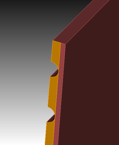
I would recommend that you start from scratch and build up a clean journal file.
