Another problem occuring while exporting the file to .g file. After exporting some of the volumes are not showing. here are the scrrenshots and .cub5 and .g file.
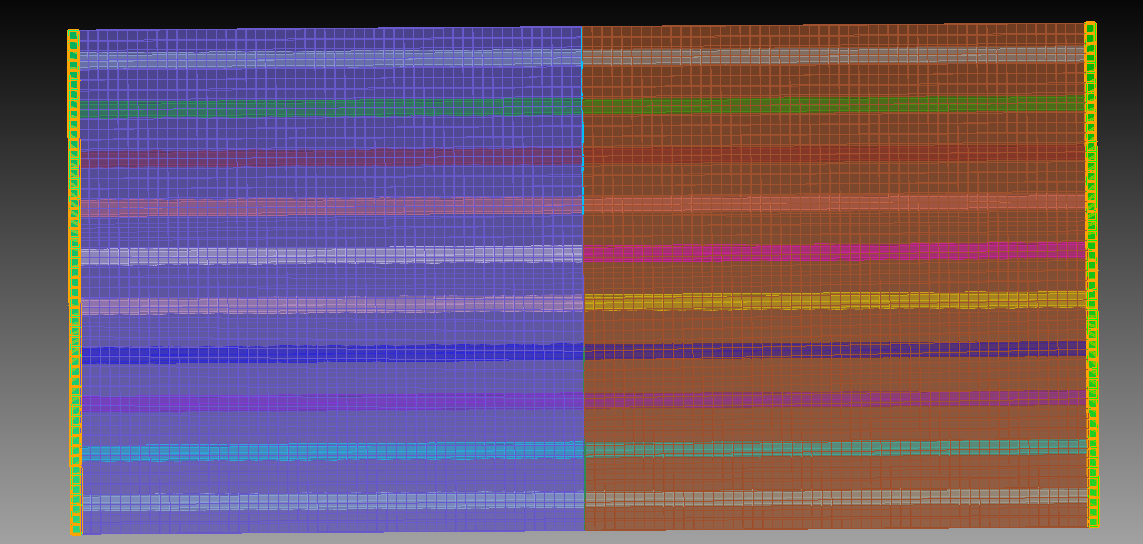
before export
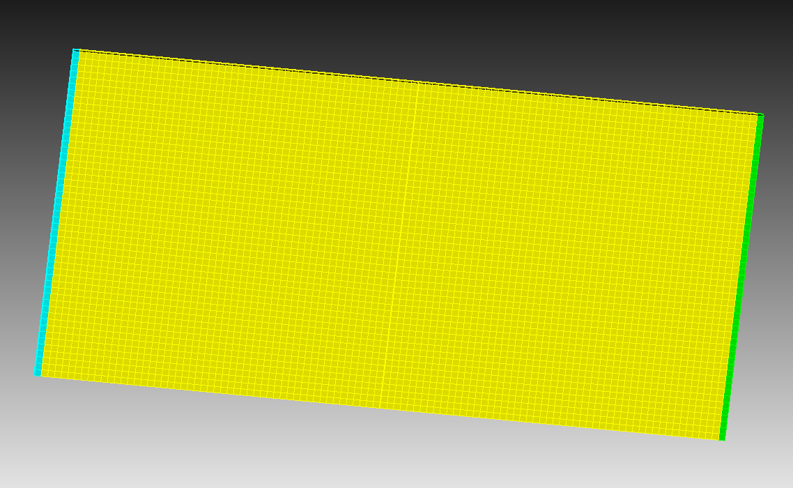
after export
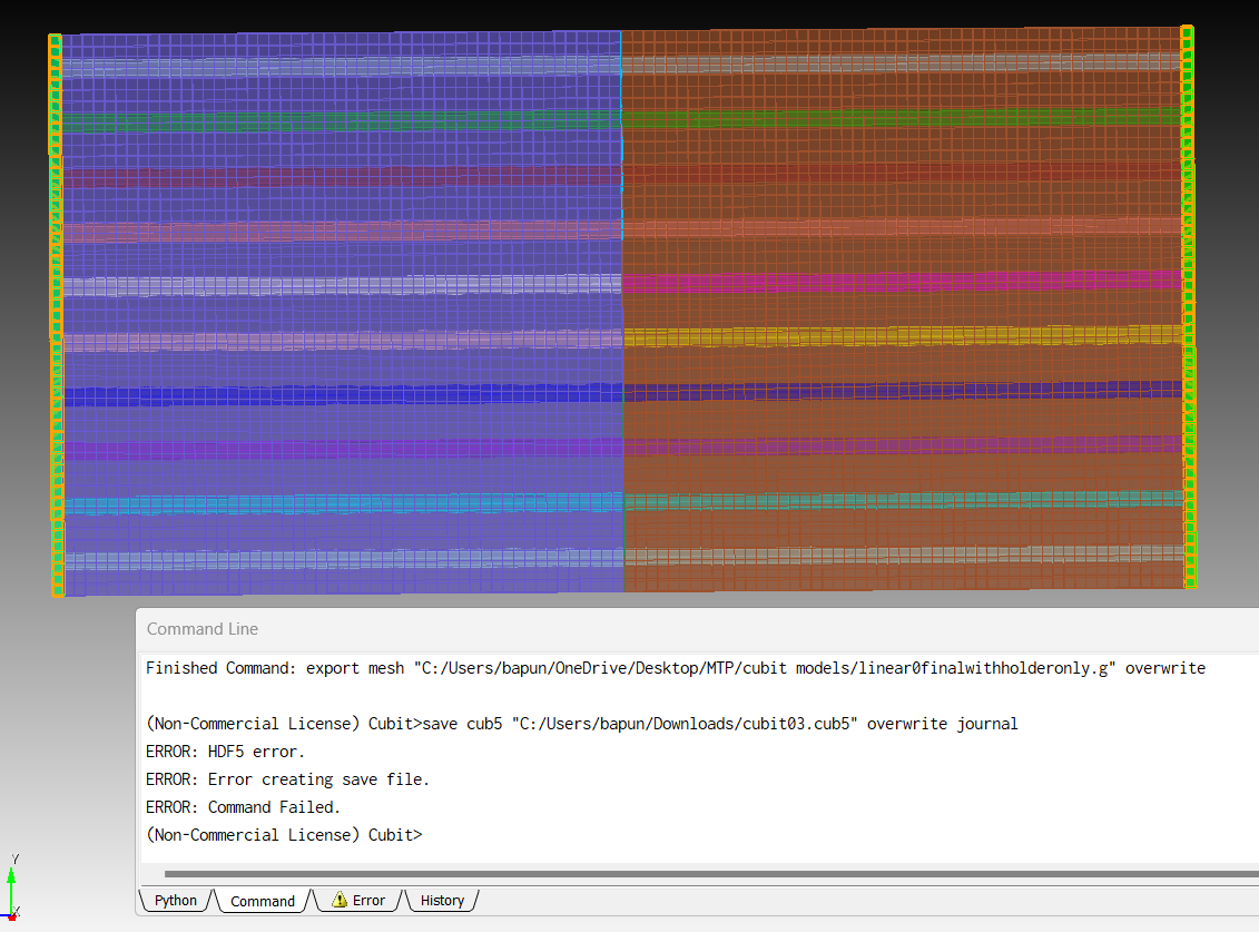
also file is not getting saved in .cub5 file
Processing: Screenshot 2023-11-10 175119.png…
Actually after running the .g file in ubuntu terminal"Terminate test that evaluated to true: volume < 0.0
**** Error: tetVolume() computed negative volume, possible element inversion or incorrect node numbering." this error is showing. Can you say why this error is showing. This is the .cub5.
With which program are you opening the .g file?
Exporting the mesh as .g file and opening with paraview works without a problem.
I would recommend to assign volumes to blocks before saving the mesh. Otherwise you will get a block for each volume.
I am using ubuntu software and running Peridigm code on that terminal. There it was showing the error that “Terminate test that evaluated to true: volume < 0.0
**** Error: tetVolume() computed negative volume, possible element inversion or incorrect node numbering.”
importing the .g file back to cubit should get you a hex mesh.
you can test if there are only hex elements when you try to draw tets
draw tet all
this should end with a warning from cubit
WARNING: No entities specified.
As you get a hex only mesh from cubit this must be an issue with the peridigm code. I guess the code is creating tets out of the hex mesh at some point and that seems to fail.
This error is happening for this model only. I had run lots of peridynamics code on previous meshing models that time it wan not showing this type of error. And in tet meshing number of elements are getting so high like it goes up to 8lacs. I want elements under 1.5 lacs.
Is it the model with the cubit01lin021fibre.cub5 from above?
could you please share your .g file which is not working.
Yes this is the .cub5 file drive file. After exporting this file to .g then after running the code it is showing the error.linear0with21fibres1.g - Google Drive
And one more problem coming while meshing a 45 degree fibre reinforced composites. I have done the meshing process as you guided. BUt some of the entities did not get meshed. Here is the .cub5 file.
cubit02e1f45.cub5 (981.1 KB)
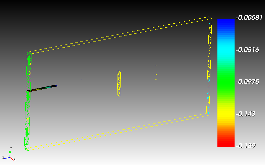
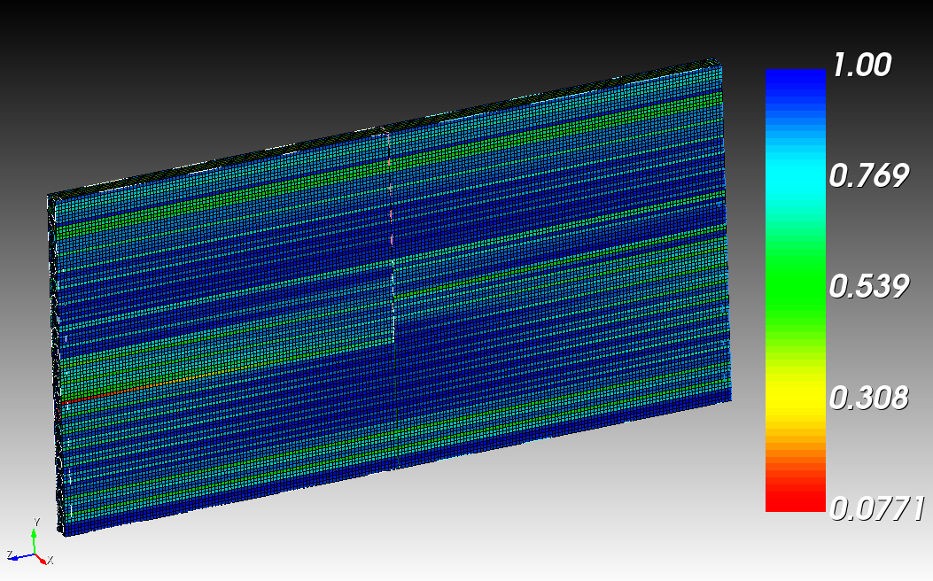
looking at your .g file and checking the quality we find elements with negative jacobians. That will definitely cause an issue.
you can do a quality check with either the gui or the command line.
quality hex all scaled jacobian global draw mesh
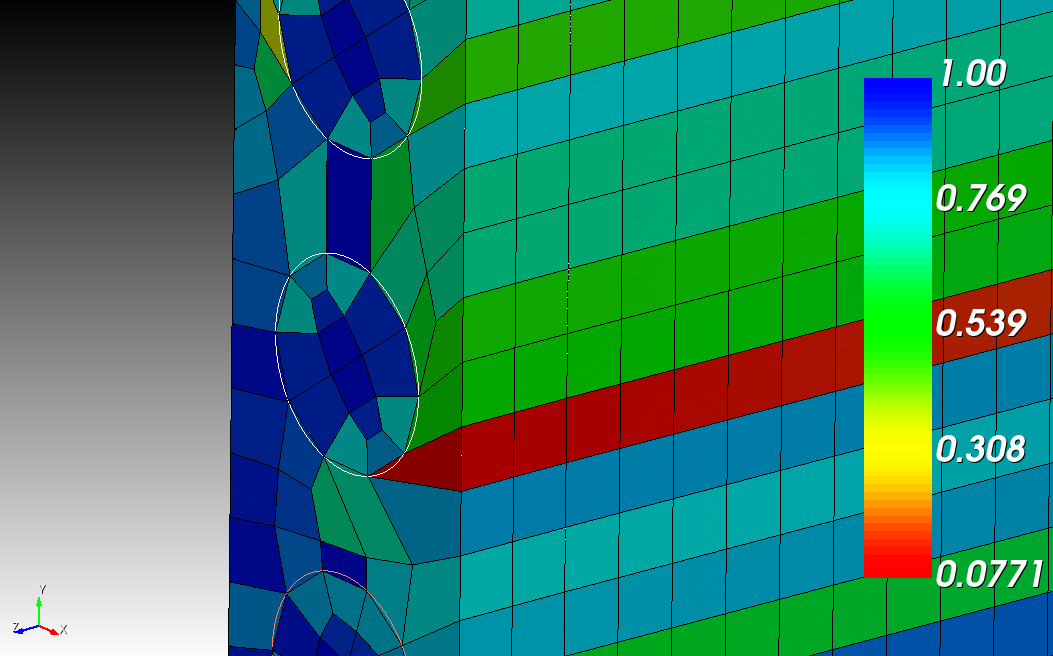
remeshing the cubit01lin021fibre.cub5 from above and doing a quality check will get us this.
open "/home/user/Downloads/cubit01lin021fibre.cub5"
delete mesh
mesh vol all
quality hex all scaled jacobian global draw mesh
which is a quality i would not be happy with. The reason for this quality is because the mesh is to coarse.
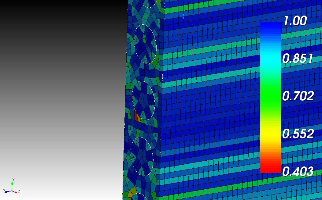
one easy fix is to adjust the mesh size and mesh it again.
delete mesh
volume all size 0.025
mesh vol all
quality hex all scaled jacobian global draw mesh
you don’t have volumes where a sweep will work. you have to decompose the geometry further or mesh with a tet mesh.
Decompose means I have to compromise with the design with the geometry? In tet meshing elements are so high and the output file will be extremely large, my pc won’t support it. Is there any options to do meshing without changing it’s geometry?
No you don’t normally have to compromise with the geometry. That’s why the creation of blocks or element sets is important for the export.
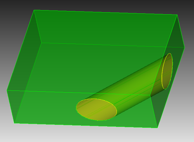
consider this example
create brick x 1 y 0.8 z 0.3
webcut volume all with cylinder radius 0.1 axis 1 1 0  center 0.5 0 0
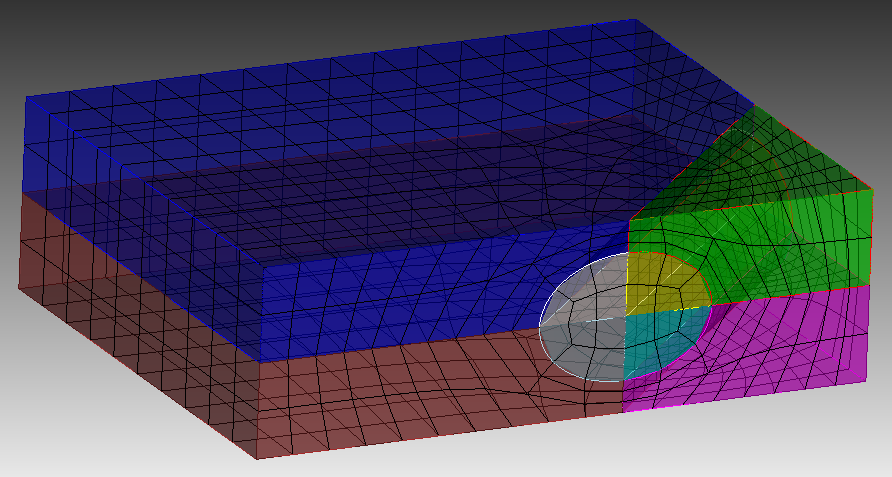
that’s a geometry that will not be automatically meshed. so we will further decompose it. normally we would aim for sweepable volumes, but that’s not allways possible but we still could aim for the polyhedron scheme.
with two webcuts we get this
webcut volume all with plane zplane
webcut volume all with general plane location curve 29  fraction 0.5 from vertex 13   location curve 49  fraction 0.5 from vertex 12   location curve 46  fraction 0.5 from vertex 12
now we can imprint, merge, set the scheme and mesh
imprint vol all
merge vol all
volume all scheme polyhedron
mesh volume all
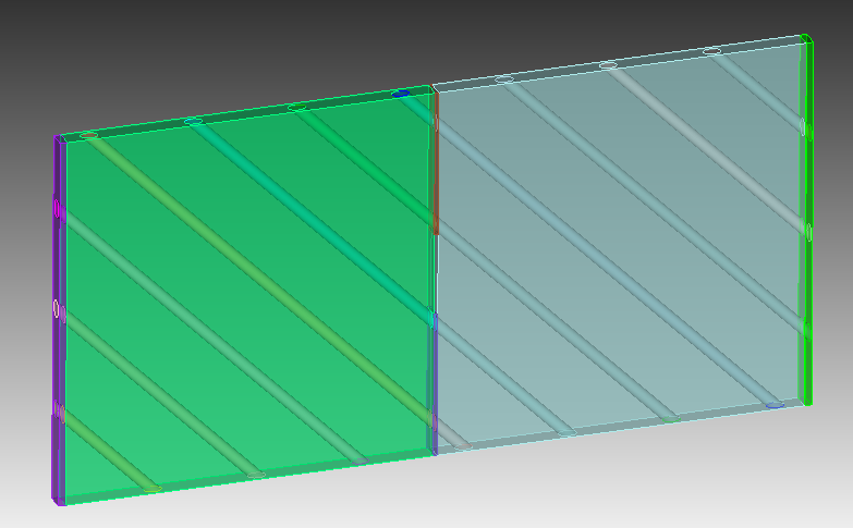
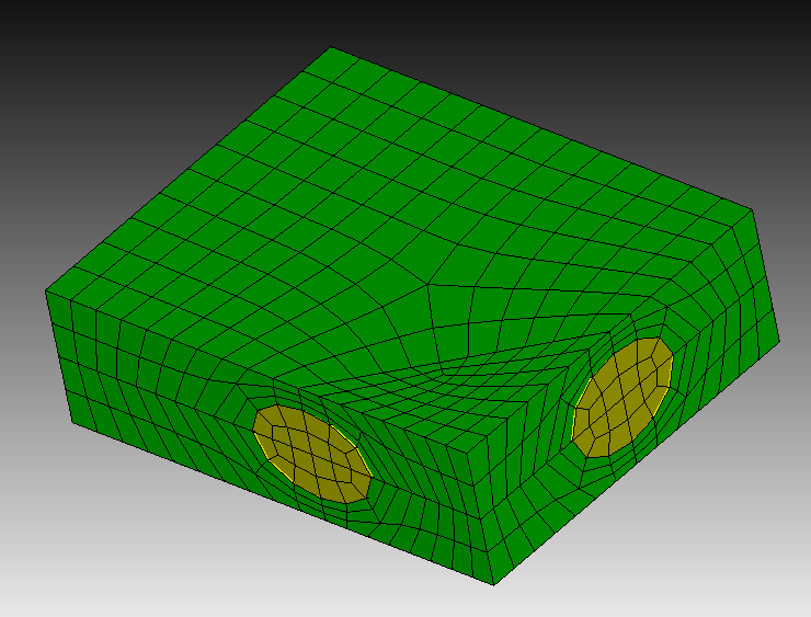
now if we only want our 2 volumes from the beginning exported in element sets, we will need to create the according blocks
block 1 add volume 1 5 7 3
block 2 add volume 2 4 8 6
draw block all
and if you don’t want to set the scheme manually. Then you will have to decompose further until everything is sweepable.
reset
create brick x 1 y 0.8 z 0.3
webcut volume all with cylinder radius 0.1 axis 1 1 0  center 0.5 0 0
webcut volume all with plane zplane
webcut volume all with general plane location curve 29  fraction 0.5 from vertex 13   location curve 49  fraction 0.5 from vertex 12   location curve 46  fraction 0.5 from vertex 12
webcut volume all with plane yplane offset -0.2 rotate 45 about z
webcut volume all with plane yplane offset -0.75 rotate 45 about z
imprint vol all
merge vol all
mesh volume all
So, like for all fibers I have to manually web cut or is there any other alternative to web cut all automatically, because after this I have to do it for like more than 30 fibers. that time it will be difficult to do so.Please give me the journal for this .cub5 file so that further I can be able to mesh for more fiber reinforced composites…
cubit02e1f45.cub5 (981.1 KB)
I don’t see a shortcut for this if you want to a good mesh.
If you need meshing services you will have to reach out to our sales team first. I am not supposed to do full meshing services in the forum support.