
About this tutorial
In this tutorial we will learn to prepare models for application in particle transport codes with the Direct Accelerated Monte Carlo (DAGMC) toolkit. To start, we’ll model a simple PWR fuel pin composed of three concentric cylinders representing the fuel pin, gap, and cladding and with a surrounding rectangular prism (brick) containing a water moderator. We’ll then look at a more complex example: a tokamak reactor.
PWR Fuel Pin
Loading geometry
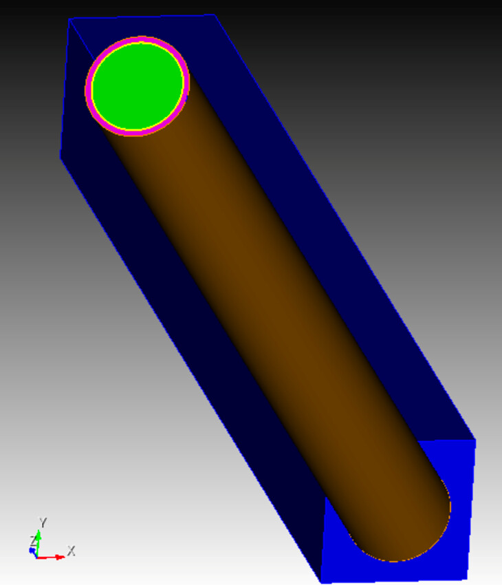
To begin, we’ll create the three cylinders with radii 0.39 cm, 0.4 cm, and 0.45 cm for the outer radii fuel pin, gap, and cladding respectively. The prism for the water moderator will have a width of 1.26 cm. True fuel pins are typically 120-200 cm in length, but we’ll model a 10 cm pin in this tutorial for clear visualization. The ACIS file for this geometry is here: pincell.sat (43.2 KB)
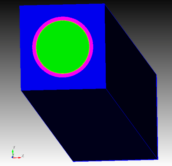
This model contains the geometry as described above with the appropriate volumes subtracted from one another to produce the fuel, gap, cladding, and moderator regions. Our task will be to prepare the geometry for export by ensuring that the faces of coincident volumes are shared (merged), mesh the model, and that the appropriate material and boundary conditions have been applied.
Checking the geometry
In order to move particles robustly from volume to volume, DAGMC requires that coincident volumes share surfaces. DAGMC leverages this topological information in the resulting triangle mesh file to change the particle’s logical containment from one volume to the other when a particle crosses the triangle of a shared surface.
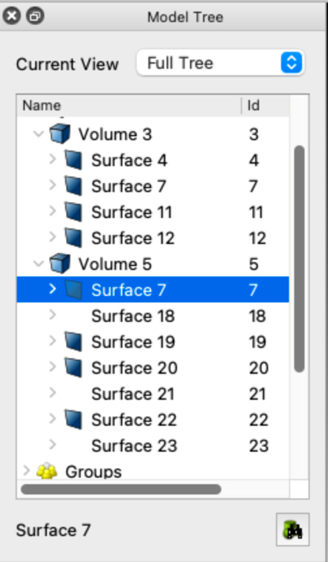
By examining the model tree (see below image), we can see that adjacent volumes do in fact share surfaces. In the image of the tree, we see that volume 5 (blue) shares surface 7 with volume 3 (pink). By nature of the final volumes in this model resulting from subtractions of other volumes, this topological consistency is guaranteed. This is not always the case, however, and as we will see later in the tutorial we may need to imprint and merge the model before moving on to metadata.
Assigning Materials and Boundary Conditions
A DAGMC model requires that all volumes have a material assignment, including void regions. To assign a material in Cubit we will create a block for each material in the model. Blocks can be created and the surface mesh of a volume assigned to the block with the following commands
create block 1
block 1 add volume 1
And a material can be created and added to this block with the following
create material 1 name "fuel"
block 1 material "fuel"
The block creation and volume assignment can be combined into one command as well
block 1 volume 1
Now we’ll repeat this for volumes 2, 3, and 5 with the material names vacuum, clad, moderator respectively.
For this simple model, that’s all there is to material assignments. Now on to boundary conditions. The method for implementing boundary conditions is dependent on the Monte Carlo code the model will be used with. DAGMC models sometimes have a “graveyard” volume surrounding all other volumes to capture and terminate all particles that reach it. We’ll be building this model for use with OpenMC, which allows us to apply boundary conditions directly to surfaces rather than create a non-physical volume.
INSERT COMMANDS FOR BC’s here
To model an infinite sea of pincells, we’ll apply reflecting boundary conditions to all exterior surfaces of the model. This will be modeled as an infinite sea of pincells in the Monte Carlo code, allowing us to compute what is known as k-inf or the neutron multiplication factor without particle leakage due to geometry boundaries.
More details on code-specific steps for creating DAGMC models can be found here.
Meshing the Model
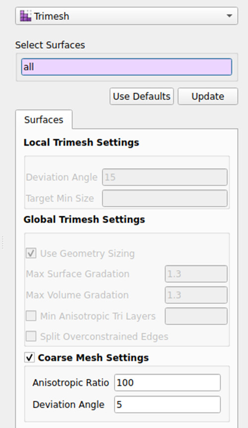
Now that we’re sure the geometry is correct and we’ve assigned our boundary conditions, we can mesh the model. We’ll use the new coarse mesh settings in the surface trimesher to do so.
-
Select
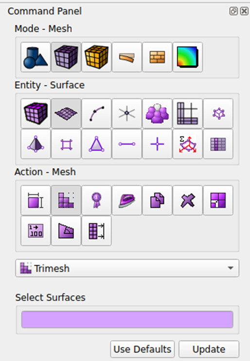
Mesh→Surface→Mesh→Trimeshin the command panel
-
Then enter
allinto theSelect Surfacespickwidget and check the box next toCoarse Mesh Settings
-
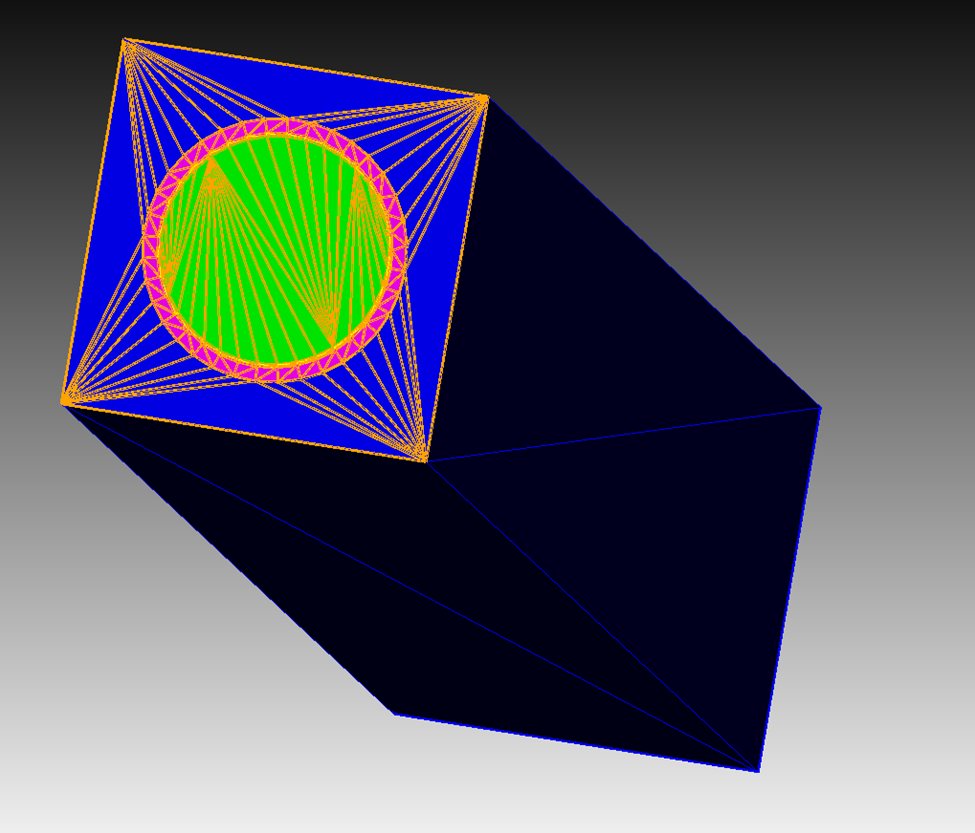
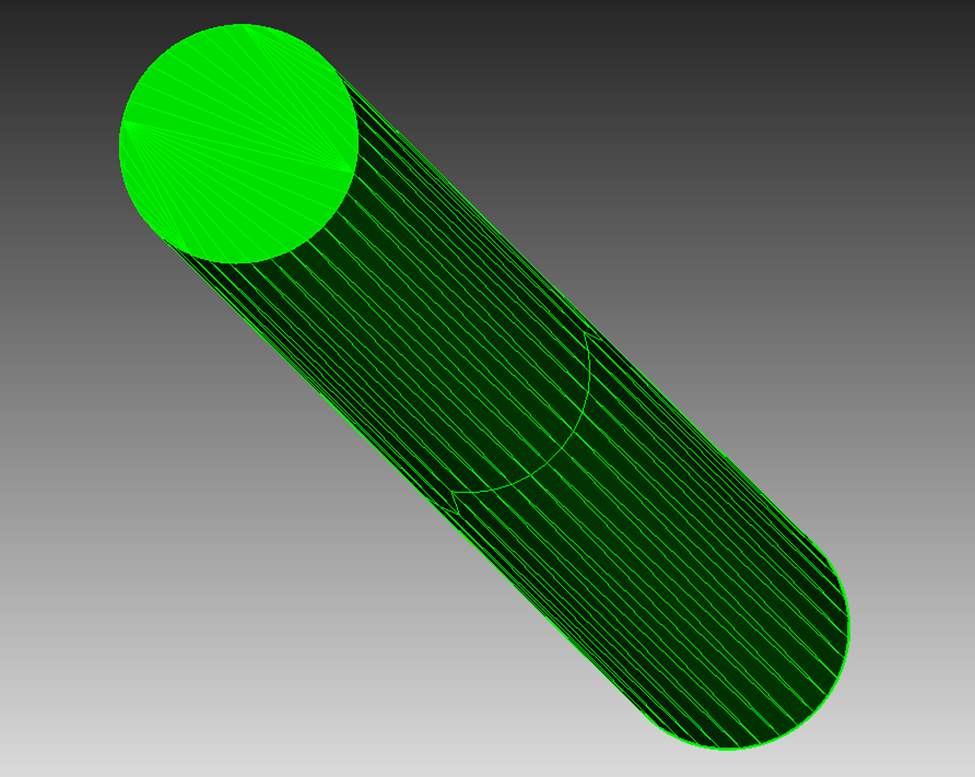
Finally, click the
Meshbutton. The resulting mesh should look similar to the mesh in the images below.
Exporting the Model
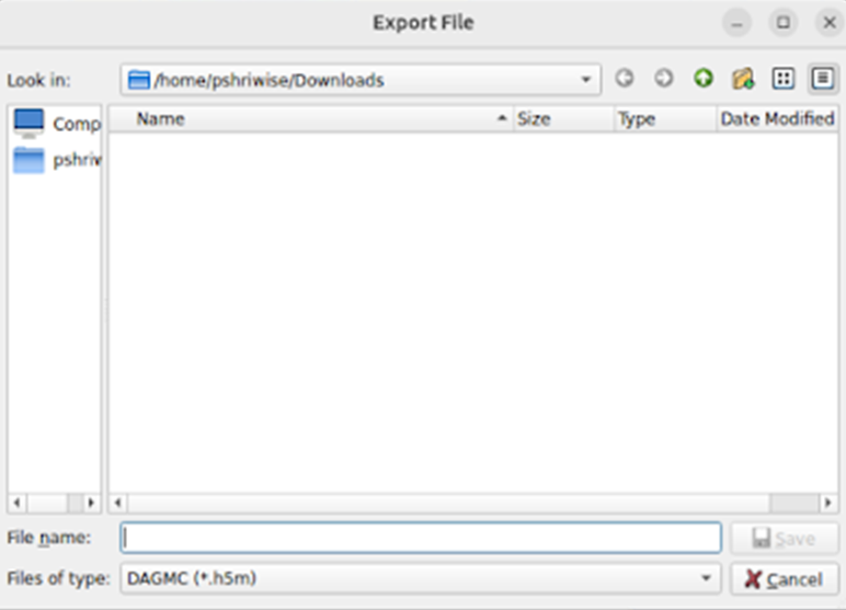
Finally, we’ll export the DAGMC model. To do so, select File → Export... in the file menu, then select the DAGMC (*.h5m) filetype, and then enter the file name you’d like to use.
This can also be accomplished using the cf_dagmc command.
export cf_dagmc "pincell.h5m"
The resulting file can now be applied in a particle transport simulation using DAGMC geometry.
Tokamak model
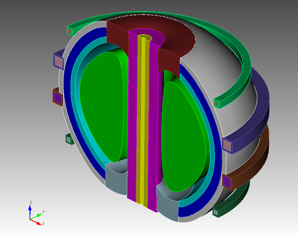
In this section, we’ll look at a tokamak model generated using the Paramak tool for tokamak design. This model contains higher order surfaces that may be challenging to otherwise model using the native constructive solid geometry (CSG) engines provided by most particle transport codes.
Select File → Open... and open the tokamak.cub5 file provided below. The following model should appear:
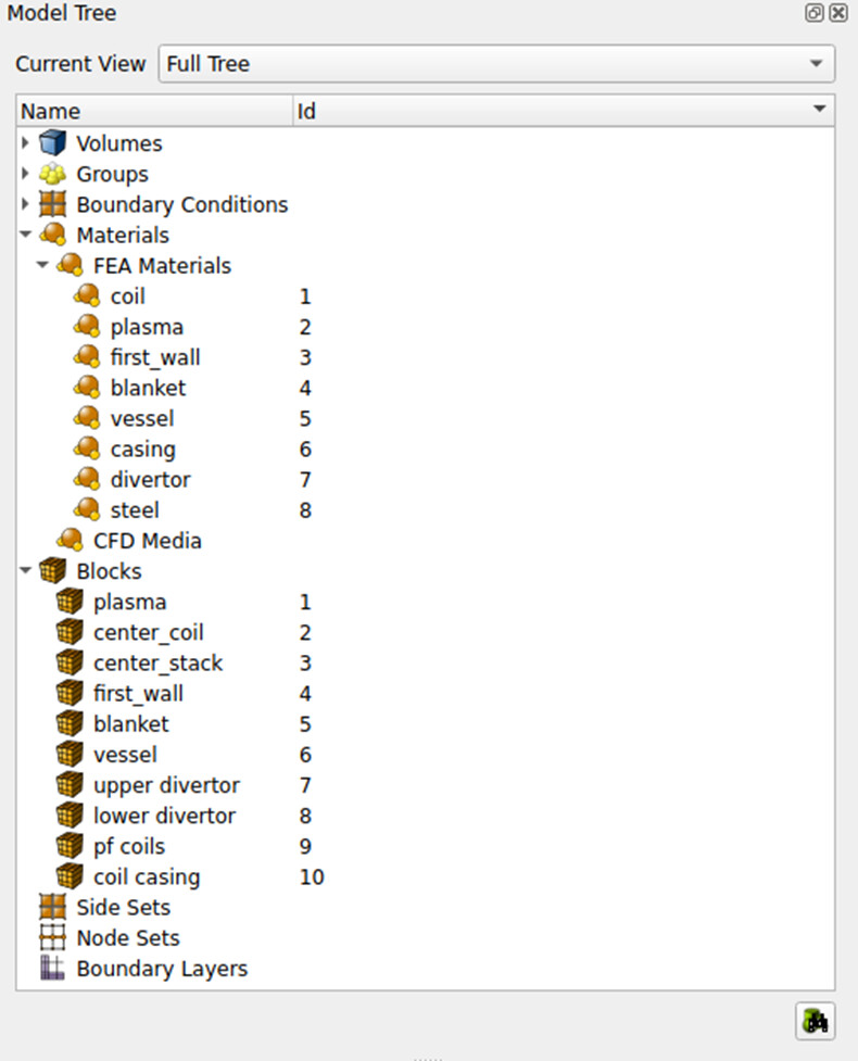
Materials have already been added to this model, so we don’t need to repeat that process:
Imprinting and merging
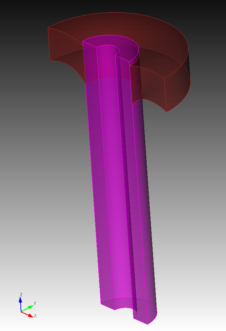
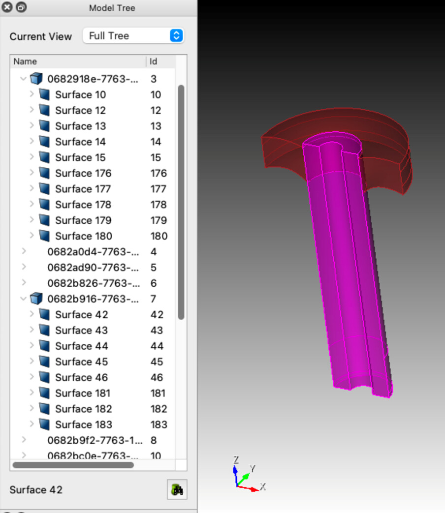
This model does need some additional work, however. Let’s take a closer look at the surfaces of volumes 3 and 7.
volume all visibility off
volume 3 7 visibility on
The model tree shows that these two do not share surfaces. Without imprinting and merging, particles will exit volume 3 (purple) crossing surface 11 and enter a space between volumes known as the implicit complement before entering volume 7 through surface 42. The implicit complement is a logical volume built by DAGMC that occupies all undefined space in the CAD model. In artistic terms it is the “negative” of the CAD bodies. Because the implicit complement is based purely on the topology of the model and surfaces 11 and 42 only have a volume on one side according to the topology, the implicit complement occupies the logical space between these surfaces.
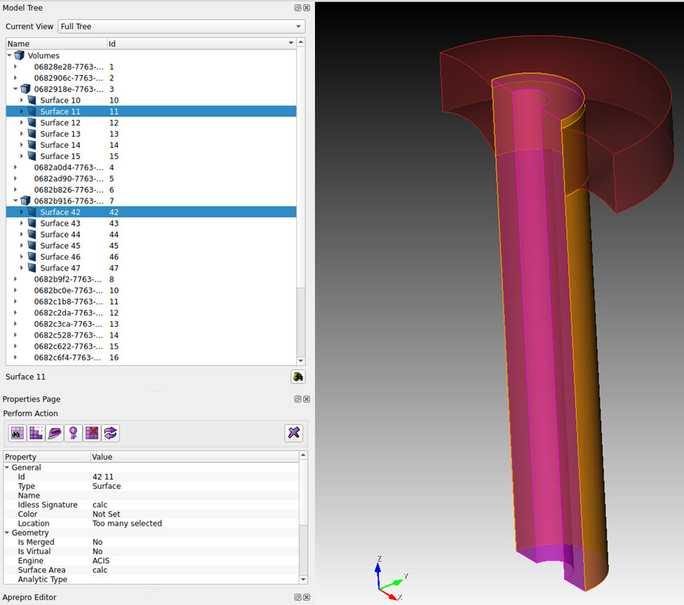
To build a robust DAGMC model, we’ll need to imprint and merge these surfaces. This will result in a single, shared surface between volumes 3 and 7 where they meet. The model topology in the DAGMC file will indicate that volume 3 is on one side of this surface and volume 7 on the other. This will allow particles to pass between the volumes efficiently and robustly during simulation without entering the implicit complement.
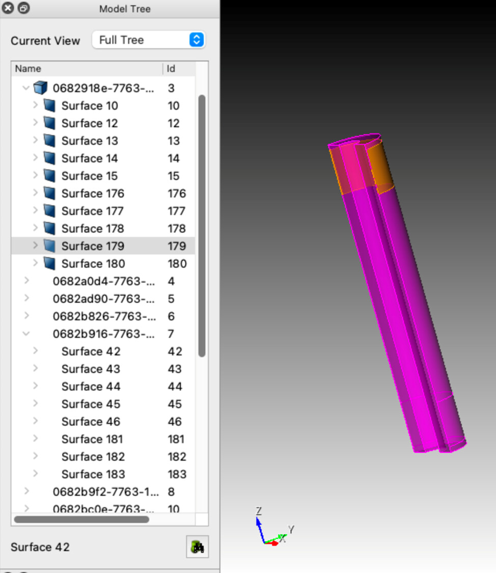
First, we’ll tackle imprinting and merging the surfaces. To imprint the model, we will run
imprint volume 3 7
Now when we examine the model tree we see many new surfaces have been added. If we now look only at volume 3, we see that one of its new surfaces,surface 179, corresponds to surface 42 of volume 7.
Surfaces 179 and 42 are still separate surfaces, however. Were we to mesh and export a DAGMC model at this point, particles would still move from volume 3 to volume 7 through the implicit complement. To create a single, shared surface we’ll merge the surfaces of volumes 3 and 7:
merge volume 3 7
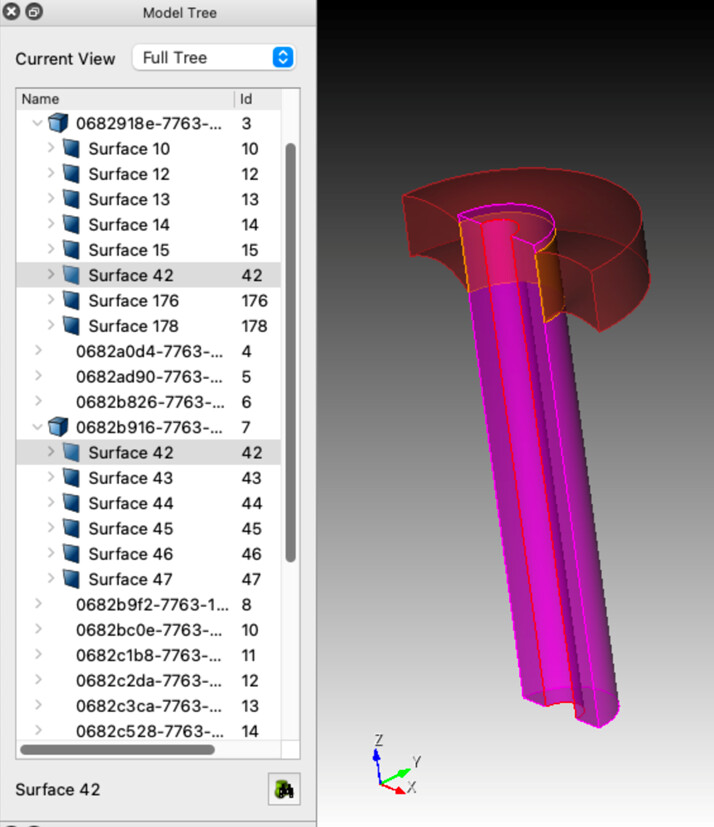
Once this step is complete surface 42 is now present in both volumes.
To create a fully robust model we’ll perform this operation for the entire model with the following commands
imprint body all
merge body all
Now that this is complete we can mesh the model as before and export a DAGMC file
export dagmc "paramak.h5m"