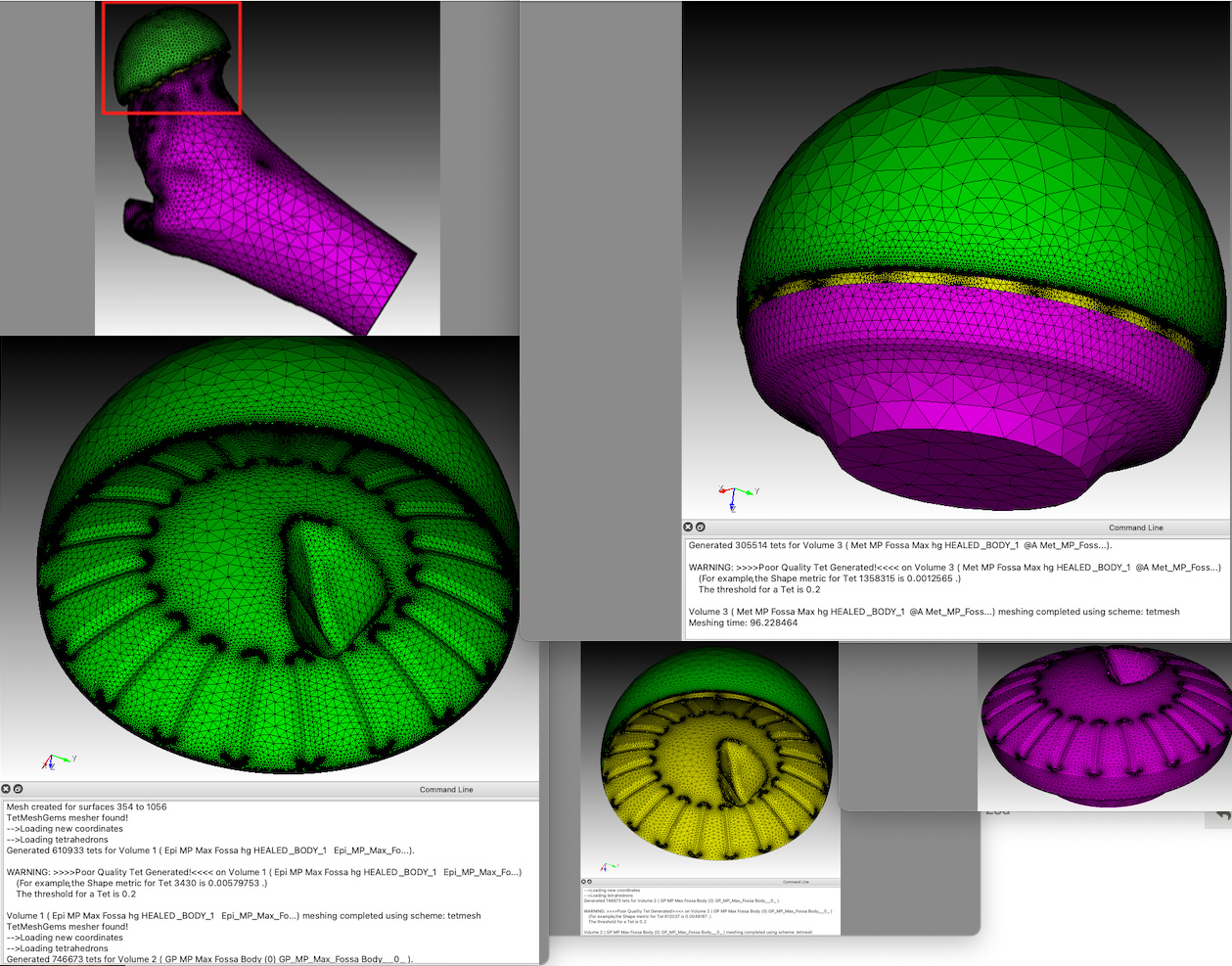
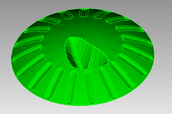
I attempted to create a usable mesh for FEA using Abaqus and have been unsuccessful for several months now and am looking for any suggestions for a workflow to create a mesh that does not result poor quality. I have since parameterized the organic geometry of a bone-cartilage-bone interface in hopes to simplify the geometry for an easier meshing process, but still haven’t had any luck creating a usable mesh for Abaqus.
I initially attempted to create blocks, side sets and node sets with the intent to create a single volume for which each section could be assigned different material properties, but couldn’t get those attributes exported/imported into Abaqus. At this point, I am just looking to mesh these parts individually with a high quality mesh that will run in Abaqus. All of my attempts create meshes that will not run in Abaqus due to poor mesh quality, as some of the tets are way below the 0.2 threshold, which I assume is why they distort during an FEA run, even with very small loads that I would not expect to cause distortion.
I tried to control the minimum size of the tets but have not been able to successfully implement a minimum size. when I set a minimum size it seems to default to this same mesh.
I just need to create high quality meshes for the 3 parts separately and I will import them separately and merge them in Abaqus. I tried to use the hex mesh as I understand them to be a more robust element, but it defaults back to the tet mesh.
The model interface is such that one surface is the imprint of the adjacent surface as the model was made using the interface surfaces as Boolean subtractions for the center segment. So far this model has proven to be stubborn one to mesh with a quality mesh, though the mesh looks like it would be exactly what I am looking for. Thoughts anyone? I would be happy to upload the STEP files if that makes suggestions easier.
I have tried to upload the files which are in stp format with the journal file in cub5 format, but it returns “Sorry, the file you are trying to upload is not authorized” though the files are .stp and .cub5. I could email them to you if there is an email address or perhaps create a link to a dropbox…
I have been trying to webcut these parts to see if I could use the “Loft Command” method, but have just starting digging into web cutting, but did attend your webinar on advanced meshing techniques. However, those were mostly for using hex elements on less complicated geometry. Tet appears to be the most useful for the geometry of these parts, but I am open to any alternatives.
It looks like the volumes exactly overlap. The regions should represent distinct volumes and not overlap. I can not get Cubit to succeed with a boolean operation because the surfaces are an exact overlap. Boolean operations are more successful if there is a bit of extension beyond the boundaries. You probably want to look at modifying these in the originating CAD system.
Thanks Karl for taking a look at these models. That is correct, the center part is just an extrusion between the upper and lower part set at a distance of 1mm space between them, and these separated part surfaces are used as the tool in a boolean subtraction to the middle extrusion to create the surfaces on the middle piece such that they are exactly adjacent to each other with the same exact matching topography. So if I understand you correctly, Cubit is not sure where to do a boolean on imprint if there is no overlap? If so, do you suggest that I extrude the two surfaces of the middle piece such that they actually overlap into their adjacent surface, and if so what distance would you recommend to make the imprint process successful in Cubit?
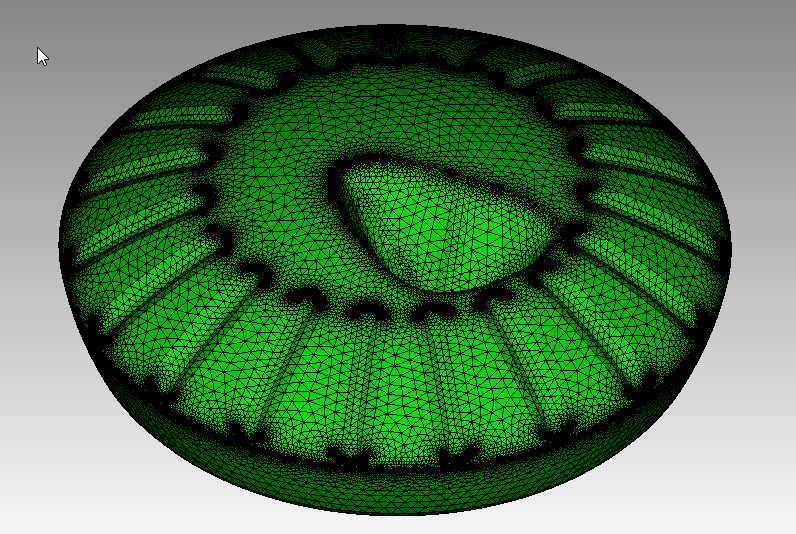
Will this work? I just did a tolerant imprint between the two volumes. The first image below shows all the surfaces in the interface are merged. You can now tet mesh these two volumes with a confomal interface.
reset
import step "Met MP Fossa Max hg.stp" heal
import step "Epi MP Max Fossa hg.stp" heal
merge tolerance .008
imprint tolerant volume all merge
draw surf with is_merged
volume all scheme tetmesh
volume all size auto factor 1
mesh volume all
This is a pretty dense mesh around the small features. You might consider compositing some of the surfaces to simplify the model.