Hello. I’m trying to mesh a small section of a long pipe that has multiple smaller pipes that are perpendicular to the larger pipe. To recreate one such main pipe-outlet junction with one large cylinder and a smaller cylinder perpendicular to it, the following .jou file can be used:
#!python

create Cylinder height 10 radius 3
create Cylinder height 5 radius 1
move Volume 2 y 8 include_merged

rotate Volume 2  angle 90  about X include_merged
move Volume 2  location surface 1  include_merged
split surface 1  with surface 4
move Volume 2  y 5 include_merged
I’m having trouble meshing the larger volume because once I create an imprint of the smaller pipe on the larger volume, and mesh the top, bottom, and curved surfaces of the larger cylinder… any sweeping/extrusion from the top to the bottom fails with the error
ERROR: Linking surface 7’s is meshed but its mesh is not regular; this is required to sweep Volume 1.
ERROR: Linking surface 8’s is meshed but its mesh is not regular; this is required to sweep Volume 1.
WARNING: Need to assign the edge types on multi-loop surfaces.
Finding Sweep Dependent Volumes…
Grouping Mesh Dependent Volumes Completed…
ERROR: Existing mesh on surface 7 (Surface 7) is not regular!
Delete mesh and change scheme to map or submap.
ERROR: Existing mesh on surface 8 (Surface 8) is not regular!
Delete mesh and change scheme to map or submap.
ERROR: Volume 1 meshing unsuccessful using scheme: sweep
ERROR: 1 volume(s) did not mesh : 1
Map, submap, and polyhedron didn’t work either.
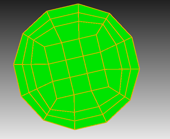
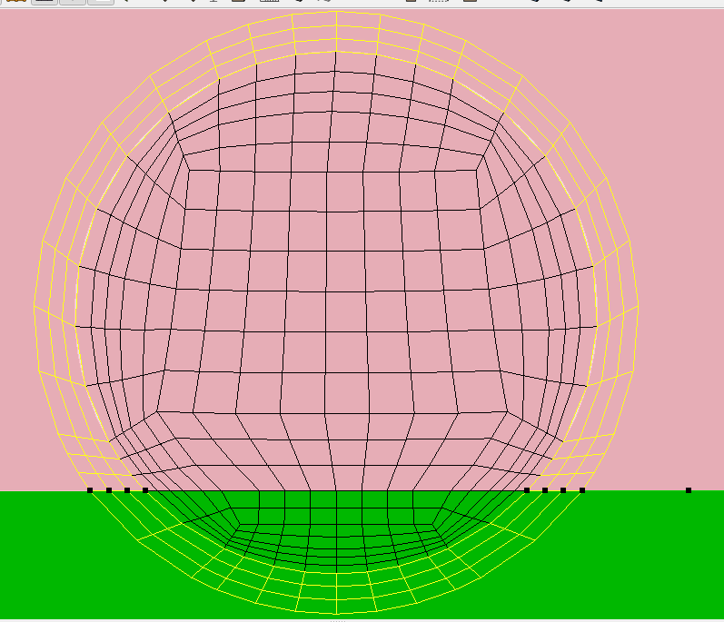
I cannot have a regular mesh (I’m assuming this means all element sizes are similar?) for the thinner pipe - this mesh is for CFD and I need boundary layers near the edge of the pipe. Could you please suggest how to create a conformal mesh for these two volumes, given that I need the cross sections of both pipes to be meshed somewhat like this?
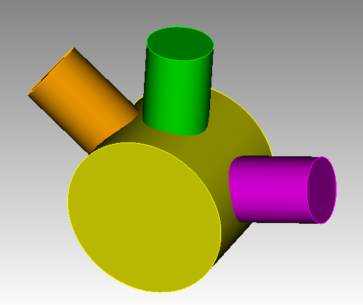
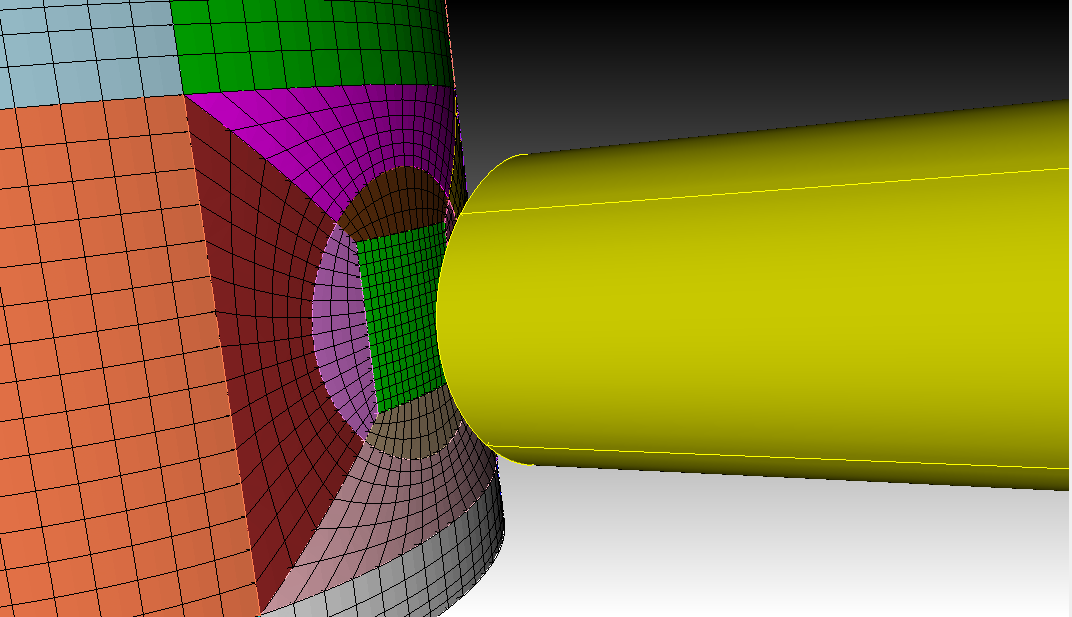
The geometry in question (exploded view) looks like the following. The mesh is just from a test attempt and not representative of what I want the actual mesh to look like
There are several ways to do this. The basic idea is that the sweeping algorithm is a fundamental hex meshing concept. If you want to sweep in two different directions you have to modify something. In this case, we sweep the smaller pipe all the way through and decompose the larger pipe so that it is a set of polyhedra.
reset

## Your original geometry creation
create Cylinder height 10 radius 3
create Cylinder height 6 radius 1
move Volume 2 y 8 include_merged
rotate Volume 2 angle 90 about X include_merged
move Volume 2 location surface 1 include_merged

## Perform webcuts
remove overlap volume 2 1 modify volume 1
webcut volume 1 with sheet extended from surface 4
webcut volume 1 with plane from surface 11
webcut volume all with plane normal to curve 21 fraction .5 from start
webcut volume all with plane normal to curve 56 fraction .5 from start

## Imprint and merge
imprint all
merge all

## Test mesh to find unmeshable regions
mesh vol all

## Add unmeshed volumes to a group to mesh with 'polyhedron' scheme
create group "polyhedron_mesh_regions"
polyhedron_mesh_regions add vol all except with is_meshed
delete mesh
volume in polyhedron_mesh_regions scheme polyhedron

## Remesh
mesh polyhedron_mesh_regions
mesh vol all
Thanks Karl. Your advice worked great for the geometry I have shared. But after meshing this minimal working example, I am trying to extend these ideas to my actual geometry of interest. I don’t have the permission to share the exact geometry here, but it’s very similar except the top surface has multiple inlet holes that also need to be meshed. Their arrangement is completely asymmetric, so there’s no way I can cut through the volume in the XY plane without creating small, irregular sections of these holes that are tough to mesh. I did try playing with creating slices in the z direction. The side view is below.
Could you please share any tips you might have on how can I create a conformal hex mesh when I’ve got the top surface with these asymmetric inlet holes (each hole has its own boundary layers) forcing a certain arrangement on the top surface of the polyhedron around the duct (2nd from the top), and the horizontal duct on the right forcing a different arrangement on the bottom surface of the polyhedron?
I tried meshing each surface then using the polyhedron scheme on the volume, but that fails with the following error:
ERROR: Volume 4 ( (Unsaved)@C 4 Unsaved@C _@C ) is incompatible with scheme polyhedron.
The polyhedron scheme works fine if I don’t try to force conformity by imposing the mesh from the top of the cylinder on the top face of the second polyhedron.
If I commit to extruding the top surface’s asymmetric mesh throughout the volume, I get extremely low quality (negative Jacobian) elements on the curved inner surface of the middle polyhedra. And after that, I don’t know how to create a conformal mesh on the horizontal duct. So that seems like a bad idea.
Can you accept tetrahedra and pyramids for your mesh or are you required to do all hexahedra?
I’m not sure I understand what you mean by “top” surface. Are you talking about something like this where all the cylinders are on the same plane? Or are the inlets not on the same plane? Do the inlets intersect when you project them through the larger tube?
I meant that the top of the larger, vertical cylinder in my previous post has various nozzles intersecting with it. I’m not meshing those nozzles. Their imprint on the top surface creates the circular inlet holes I mentioned. There are just two cylinders, the ones shown. The larger one has those asymmetric inlet holes on the top and a wall at the bottom and on the sides. The smaller, horizontal one on the right has one big outlet on the right. The flow enters through the holes on the top surface of the larger, vertical cylinder, and leaves through the smaller, horizontal cylinder on the right.
Rather than cut along the XY plane, try cutting on the XZ plane between the inlets. Push the outlet pipe all the way through like you have done. Try not to cut the outlet pipe if possible.
Would the outlet pipe have more than two intersecting sections?
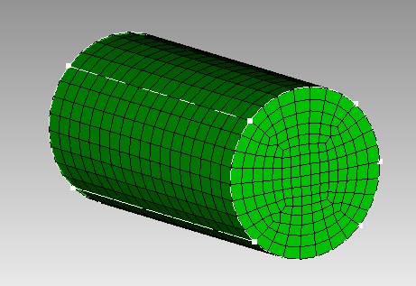
Here is a technique for turning the outlet pipe into a mapped mesh. Split the surfaces of the cylinder so there are four preferably equal sections. Place a mapped mesh on one of the squares. Pillow around the cylinder to move the poorly shaped elements away from the edges. The resulting quality is very good.
You can then sweep down around the mapped mesh.
reset
create cylinder radius 2 z 8
split surface 1  across location curve 2  fraction .125 from vertex 2   location curve 1  fraction .875 from vertex 1
split surface 4  direction curve 3
split surface 5  direction curve 3
Surface 3 scheme map
mesh surface 3
mesh volume 1
pillow hex in face in surf 9 8 6 7 through surf 3 2
pillow hex in face in surf 9 8 6 7 through surf 3 2
smooth volume 1
volume 1 smooth scheme mean ratio
smooth surf all
smooth vol 1
quality vol 1
Thanks. I have been using this idea to divide my overall geometry and proceed with extrusion. But I am currently encountering conformity issues because of the following problem with my boundary layers.
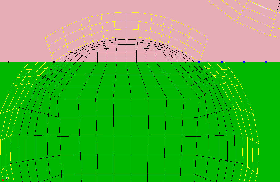
I have these thin sections of holes formed because I cut my geometry in the XZ plane, as suggested. I am meshing these small sections separately, exporting them as exodus meshes, and copying them onto the thin slices shown below in my larger geometry, after which I am creating boundary layers.
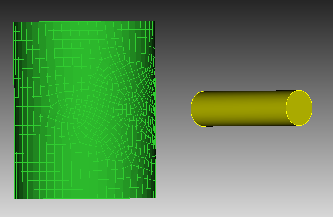
In most cases, the boundary layers are formed as expected. See the case below, where the circle’s area is split 85%-15%:
However, in a couple of cases, I have a situation similar to the picture above except the split is 90%-10%, i.e. the thin slice is smaller. That results in the following boundary layers, even though I am copying the same meshes onto these surfaces, and the boundary layers have identical settings:
Is there a way to get the second boundary layer to be more like the first case so that I have conformal meshes across the two volumes, with no gap between these two sets of boundary layers? I have tried refining the thin slice but it’s not working.
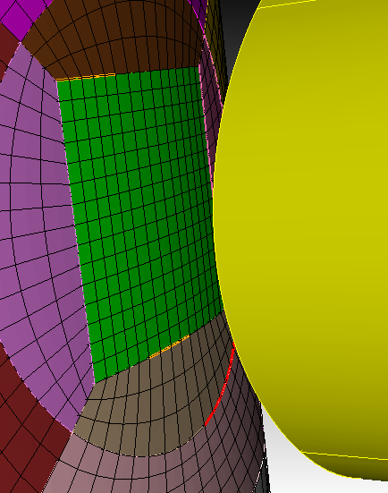
Thanks for your tips, I was able to extend your idea, find a couple of workarounds and mesh the geometry. But I’m seeing some strange errors at the junction interface between the vertical and the horizontal pipes.
I’m copying meshes between surfaces at the junction from the larger pipe to the smaller pipe for conformity. They have the same topology. The mesh copy is successful (the source/target curves and vertices look correct), and the copied meshes look correct. But when I do a coincidence check, it does not show coincidence unless the tolerance is lowered to 1e-3. I’m doing multiple surface mesh copies across other surface pairs and they are all coincident up to 1e-6, but at the junction between the two pipes, the copies don’t seem to be as accurate and conformal as everywhere else.
Could you please let me know if you have any ideas as to why this may be happening, if you’ve ever encountered this before?
I haven’t encountered that case before The copy is likely creating new nodes at the copy location. If everything looks like it lines up, you might try equivalencing the coincident nodes. In the GUI this is under Mesh/Nodes/Equivalence.
From the command line do equivalence node all tolerance 1e-3
After executing that command, I get 0 nodes merged: 0 retained and 0 deleted. And 1065300 nodes unmerged and unchanged.
I guess it’s not working. In theory, after executing this command, if I do a coincidence check with a tolerance > 1e-3, I should see all nodes as coincident? That isn’t happening.
These conformity issues seem to exist across source and target surfaces of a mesh copy, both have the same topology.
Are you copying meshed geometry or only the mesh? If you are copying the geometry, try doing a merge all instead of the equivalence. In this simple case the merge works.
reset
cylinder radius 2 z 2
volume 1 copy move z 2
mesh volume 1
volume 2 scheme copy source volume 1 nosmoothing
mesh volume 2
topology check coincident node node all tolerance 1e-06 draw brief result group
display
merge all
topology check coincident node node all tolerance 1e-06 draw brief result group
The command window should print “Found no coincident node pairs” after the second coincident node check.
I’m sorry, that didn’t work. The command does print what you wrote, but when I go to my CFD solver, I’m getting the same errors as before. The CFD solver is recognising the problem area at the interface as an external boundary that’s non-conformal, instead of the interior of the mesh. There are no gaps in the geometry, according to both Trelis and my CAD software.
I’m not sure how I can copy the geometry and the mesh, or what that means. I can describe what I am doing as follows. The exploded view of the junction is below
Since mesh copies seem to work only if both the target and the source surfaces have identical bounding curves, I’m creating a similar geometry on the target surface (say, the square in the middle of the pipe on the right) by breaking up the bounding curves at vertices that correspond exactly with the source surface’s bounding curve endpoints. Or if the import of the step file created some oddly split curves (a quarter of a circle split into two halves), I’m creating composite curves out of those curves to match the source surface. Once the bounding curves match, the surface mesh copy succeeds.
This strategy has worked across most flat surfaces of the 18 volumes I have. However, it’s only this curved interface that is creating problems. Is the curvature of the source or target surfaces or the presence of composite curves a factor? Do these details provide any new insights? Please let me know if that’s the case.
Thank you.
EDIT: To answer my own question, I meshed a flat square that was very close in size to the two squares seen at the end of these volumes. I copies the mesh from the flat square to these two curved squares. They are still not coincident.
The merge will fail if the geometry has discontinuous curves on one side and not the other. The purpose of imprinting to to make sure that the curves are identical across the boundaries. Are the geometries identical across the boundaries?
I would think that by imprinting and merging the smaller cylinder onto the larger cylinder, you should get what you want. I will try to replicate an example of this problem later today.
Thank you. That makes sense and I think that is the source of the problem. I tried imprinting surface-with-surface at first, but being a relatively new user, I was discouraged by some warnings that look like: WARNING: problem splitting face
So instead I created some free curves and vertices by copying geometrical entities from the source surface, that I used to imprint the target surface. While the imprint with curves didn’t result in the warning above and geometries across the surfaces looked identical to the eye, closer inspection revealed they don’t line up exactly.
I tried imprinting directly with the source surfaces, and despite the warning the imprint does look successful. I’ll retry meshing the geometry.
In a solid mesh, try imprinting volumes and not at the surface level.
One workflow that I have seen is that the user will get everything set up and try to mesh everything
mesh volume all
If that succeeds, you know you have at least a chance at success. Then do
delete mesh
imprint all
merge all
mesh vol all
Imprinting and merging will create additional constraints on the mesh. You may have to modify the geometry more to get a valid hex mesh on the imprinted geometry.