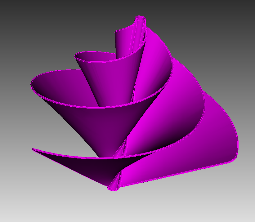
I have acquired a generic turbine to try out a comparison between my Abaqus evaluation and my Coreform _IGA trials (geometry comes from GrabCad). Each of the interior facing surfaces of the turbine has a 5 psi pressure applied to it (there are 3 blades in this design). FEA took about 400k- 600k 2nd order tetrahedral elements to mesh confidently. With the Coreform_IGA flex method I choose ~18k 2nd order elements for a first test.
Typical aluminum properties: Modulus - 10e6 psi, Poisson’s ratio - 0.33
Boundary condition is held in all 3 DOF through the center of the turbine blade.
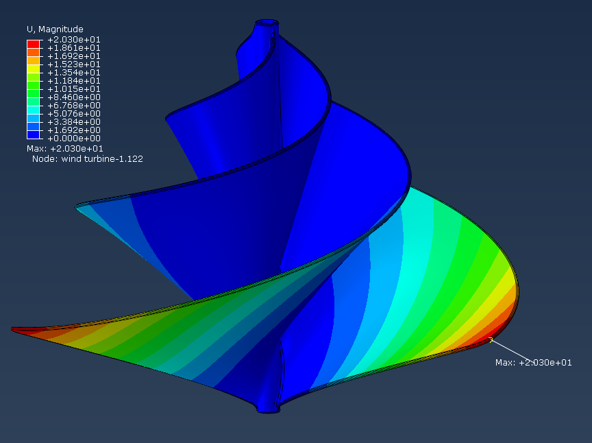
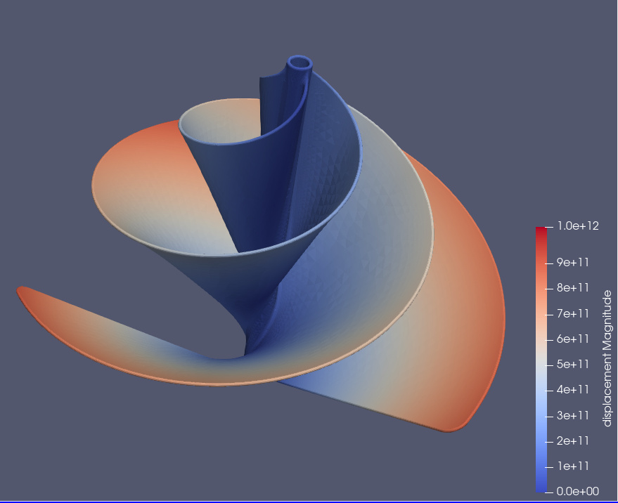
Upon looking at the results there seems to be a discrepancy between the FEA result and the IGA result. FEA predicts a maximum displacement of ~ 20.3 inches whereas the IGA predicts 1e12 inches.
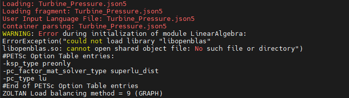
Perhaps I am missing something in the setup? I am getting an error in my job execution about the linear algebra library no loading. Could this be a/the problem? Json5 file attached for convenience.
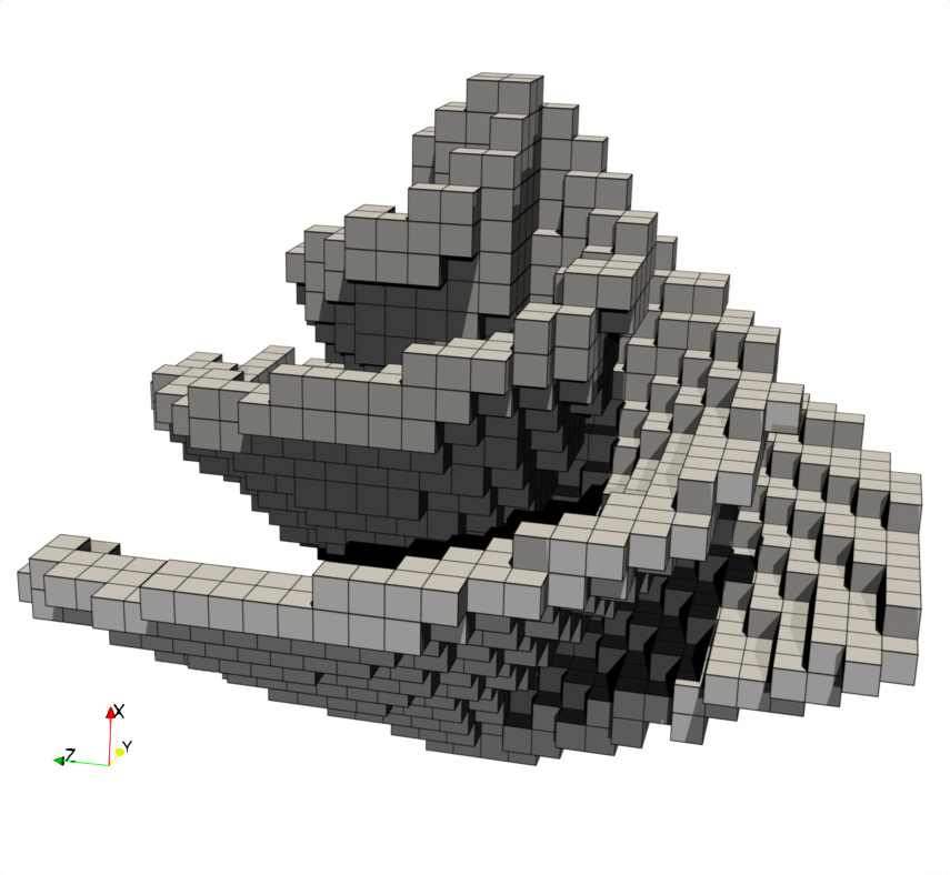
And just to follow up - as I’m sure you’ve seen, the displacement is still a fair bit off (14 vs 20.3), but I thought I’d take a deeper look. As you’ve mentioned the entire envelope domain was meshed with 18k Bezier elements, however, if you open the Turbine_Pressure_envelope.pvd file you will see only the elements that contain part of the physical domain – there’s only 1972 of these elements.
This is a great example of why we’re working on local U-spline adaptivity. But I’m also quite impressed that this result is as “close” (less than factor of 2) as it is, considering its coarseness (again, there’s really only 2k Bezier elements involved in the calculation).
Indeed a very coarse mesh when looked at it from the perspective of ‘working elements’. I look forward to a local adaptivity. I might try a third order approach to this problem. Although that cubit process will be left to happen over night as the uspline operations on this particular design took a long time. I will see what happens and update as I see new results.

 Sigh… I could blame the children, but that wouldn’t be right. Thank you =D