
A question that has come up is how to use the Advanced option: Insert mid-nodes during meshing in the Tetmesh meshing scheme. In particular, this option doesn’t insert mid-nodes if the volume being meshed hasn’t been assigned a higher-order tet element type, e.g. TETRA10. Let’s look at an example so we can see how this all works.
Example
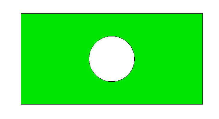
Geometry file: plate_with_hole.sat (25.5 KB)
Import the model:
reset
import acis "plate_with_hole.sat" attributes_on  separate_bodies
Let’s use a coarse mesh size so we can more easily discern behavior:
volume 1 size auto factor 10
And let’s also request visualization of nodes:
node visibility on
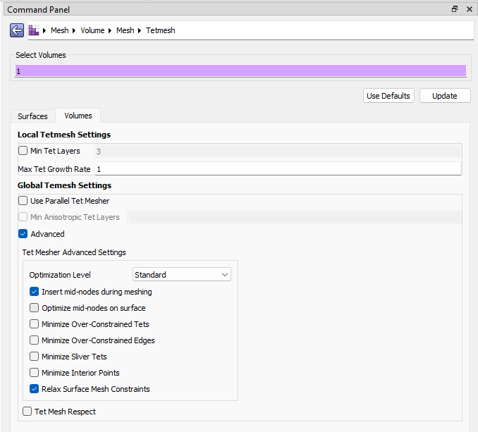
In the GUI, we can apply the Tetmesh scheme with the option to Insert mid-nodes during meshing. Note that in the image below I’m using our alternative “Breadcrumbs” layout:
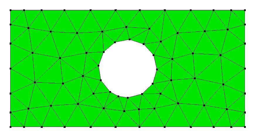
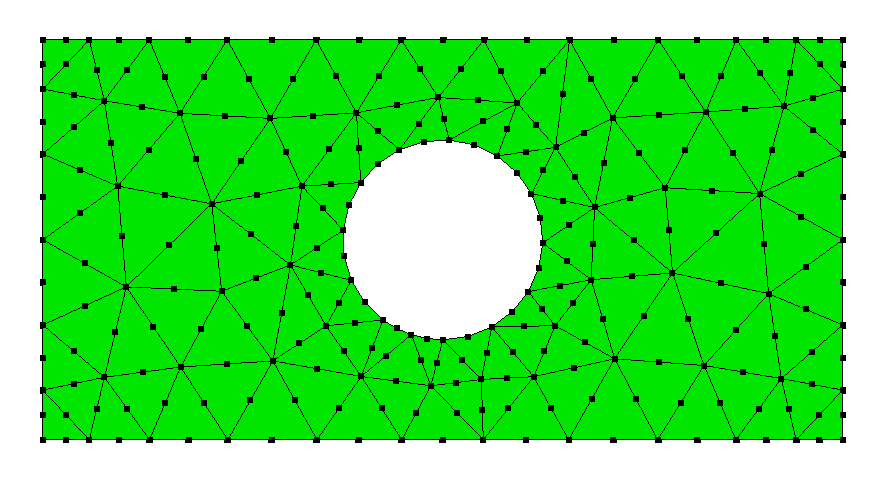
If we use these settings, we’ll get a mesh that doesn’t look like it has any mid-nodes, which is because it’s a linear tet-mesh:
The reason for this is that Cubit uses Blocks to define element regions (sets) upon which the analyst can later apply materials onto, or to specify the element type. By default, if the user hasn’t specified a block Cubit creates meshes with linear elements (for performance purposes).
To create a block we can run:
block 1 volume 1
If we select the block within the model tree, it will become the active entity within the Properties Panel which I’ve undocked from its normal location in the image below. Notice how there’s an entry for Element Type:
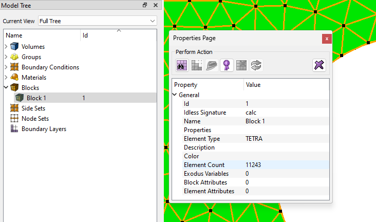
If we click on the TETRA value we’ll get a drop-down which allows us to choose our element type:
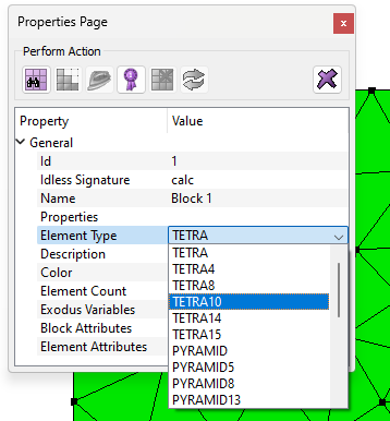
Choosing TETRA10 then issues the command:
block 1 element type TETRA10
And our model will update with mid-nodes:
But notice that this happens after the meshing algorithm is complete. If we instead first create our block and assign the TETRA10 element type, then the mesher will insert these mid-nodes during the algorithm. This allows us to also choose the Advanced option: Optimize mid-nodes on surface.
Here’s a full script for your testing pleasure:
## Import geometry
reset
import acis "plate_with_hole.sat" attributes_on  separate_bodies

## Turn on mesh-node visibility
node visibility on

## Assign volume to a block and give quadratic element type
block 1 volume 1
block 1 element type tetra10

## Define mesh settings
### Target mesh size
volume 1 size auto factor 10
### Assign Tetmesh scheme
volume 1 scheme tetmesh
### Tetmesh specific settings
set tetmesher add mid_edge_nodes on
set tetmesher optimize surface mid_edge_nodes on

## Generate mesh
mesh volume 1