Hi,
I am trying to build a model of the human thorax with the tissues inside. I do the FEM analysis after I build the geometries. We developed an algorithm to build the AORTA geometry in Cubit.
But, e.g., the thorax has been reconstructed from a CT scan, simplified in Meshmixer and then inserted into Cubit. For my FEM simulation, I have to subtract the aorta from the thorax to define two different material properties, but CUBIT does not allow this and gives me this error “Performing SUBTRACTION with volumes containing geometry from different modelling
engines is not allowed”. Can anybody help me in this regard on how to solve this problem?
Welcome to the forum. As you noted, Cubit does not support subtracting Cubit geometry, built with ACIS, from facet-based geometry, imported via STL files.
However, there is a tet-meshing option that accomplishes a similar task. The command
allows us to specify triangles on the surface of the aorta that will be included or respected while meshing the thorax.
You can read more about the tetmesh respect command in the online documentation 5.4 Meshing Schemes (coreform.com) in the section labeled 5.4.12.19.5 Conforming the tetmesh to internal features.
One thing to note, if you remesh the aorta surfaces without doing a reset, you should issue a command of the form
volume <ids> tetmesh respect clear
to ensure that you don’t have old triangle ids in tetmesh respect command.
The model that I use here is obviously simplified, but it should show the fundamental ideas.
reset
# create the "aorta" as ACIS geometry in Cubit
create curve arc radius 1 center location 1 0 0 normal 0 0 1 start angle 0 stop angle 180
create curve location vertex 2 location 0 -10 0
create surface circle radius .25 yplane
undo group begin
sweep surface 1 along curve 1 keep individual
delete curve 1
undo group end
undo group begin
sweep surface 1 along curve 2 keep individual
delete curve 2
undo group end
delete body 1
unite body all
compress
volume 1 name 'aorta'
# jump through some hoops to create facet-based geometry representing the thorax
set geometry engine facet # go into facet-based geometry mode
set developer on
brick x 5 y 14 z 5
vol 2 move y -4
vol 2 move x 1
set developer off
set geometry engine acis # go back to acis mode
volume 2 name 'thorax'
# do the actual meshing
aorta size .5
aorta scheme tetmesh
mesh surf in aorta
thorax size .7
thorax scheme tetmesh
# this command is used instead of a Boolean subtraction to define the boundary of the aorta
thorax tetmesh respect tri in surface in aorta
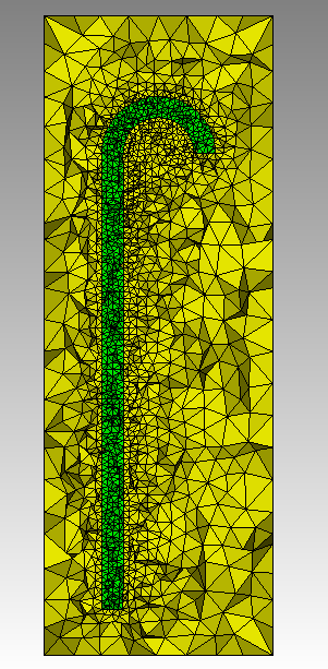
mesh volume all
draw tet all
graphics clip on direction 0 0 -1
graphics clip manipulation off
#graphics clip off
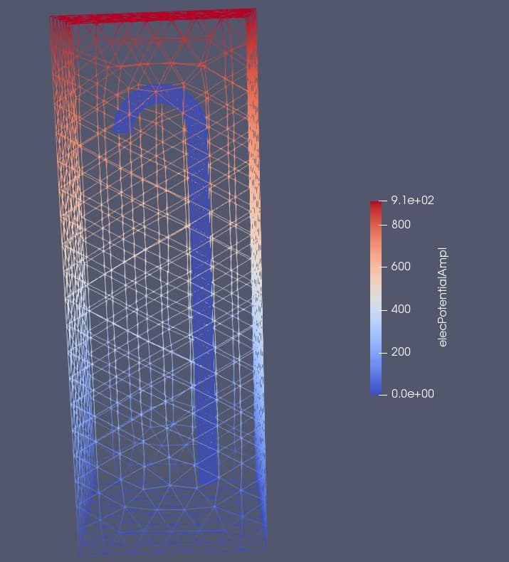
Thanks a lot for the tip. In order to solve the PDE based on the generated mesh, I must subtract the aorta geometry from the thorax domain, so the aortic part will be excluded from the thorax domain, to be assigned with the proper material property of its own. I.e., there should be a surface defined between the thorax domain and the aorta after subtraction. Otherwise, it does not work. Please look at the attachment; there is no solution for the aortic part because of that.
Do you want to apply material properties on the surface of the aorta? You can create Cubit blocks to represent element sets for material properties and element properties.
Block 3 will contain the triangles on the surface of the aorta. You could represent those as shell elements in your solver.
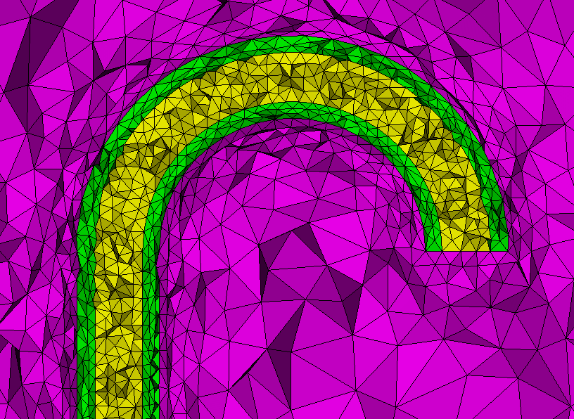
If you want the aorta to be a thick-walled object, you could change the circle creation at line 6 to create an annulus
create surface circle radius .25 yplane
create surface circle radius .15 yplane
subtract vol 2 from 1
compress
Also, you will likely want multiple tets through the thickness of the aorta. You may need to decrease the element size and turn on anisotropic layers before meshing.
set tetmesher anisotropic layers on 3
mesh volume all
The blocks for the separate volumes should be created on export. You may still want to create the blocks manually, so you know the element groups you are working with in your solver. There are a couple of other changes. I’ve included the full thick-walled solution below.
For your aorta, you would need the aorta and the interior blood as separate volumes.
reset

# create the "aorta" as ACIS geometry in Cubit
create curve arc radius 1 center location 1 0 0 normal 0 0 1 start angle 0 stop angle 180
create curve location vertex 2 location 0 -10 0
create surface circle radius .25 yplane
create surface circle radius .15 yplane
subtract vol 2 from 1 keep_tool
sweep surface 3 2  along curve 2 1   keep
delete body 1 2
delete curve all
imprint all
merge all
compress
volume 1 name 'aorta'
volume 2 name 'blood'

# jump through some hoops to create facet-based geometry representing the thorax
set geometry engine facet
set developer on
brick x 5 y 14 z 5
compress
volume 3 name 'thorax'
thorax move y -4
thorax move x 1
set developer off
set geometry engine acis


# do the actual meshing
aorta blood size .3
aorta blood scheme tetmesh
mesh surf in aorta blood
thorax size .7
thorax scheme tetmesh
# this command is used instead of a Boolean subtraction to define the boundary of the aorta
thorax tetmesh respect tri in surface in aorta
thorax tetmesh respect tri in surface in blood
set tetmesher anisotropic layers on 3
mesh volume all
thorax tetmesh respect clear
draw tet all
graphics clip on direction 0 0 -1
graphics clip manipulation off
#graphics clip off
Dear Karl.
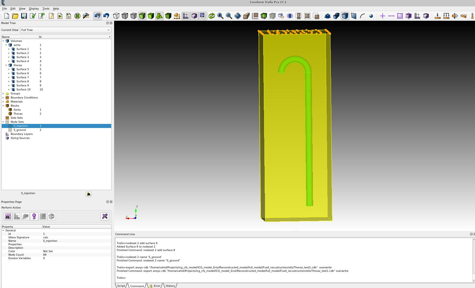
Thanks again for your quick responses. If I want to specify my point, there must be a common surface between the thorax domain and the organs, as is visible in the picture. I can subtract the Heart from the thorax by “subtract heart from thorax imprint keep”, then a new geometry of thorax is generated in which the heart shape is subtracted from the thorax domain, thus, building a common surface, ‘heart surface’ after merging in both thorax and heart volume. That’s basically what I need to do with the aorta as well, but the subtract command can not manage this. I do not need to model the aorta’s wall
and am familiar with making blocks. I attached the CUBIT file; maybe that helps if You look into it. Thanks. Thorax_model_test.zip (9.7 MB)
I think I may have a fundamental misunderstanding in your requirements. Normally, after the boolean operation, we would do imprint and then merge to ensure a conformal mesh between the two bodies. Do you want separate surfaces between the thorax and the organs so that you have duplicate nodes on the surfaces between the organs and the thorax?
Perhaps the easiest thing would be to just convert the aorta to STL.
export STL 'aorta.stl' tri in vol 49
del vol 49
import stl "./aorta.stl" feature_angle 135.00 merge make_elements
then do the subtract like you did the heart.
I would be cautious about doing the boolean subtract on the facet-based models. This is only likely to work so long as there are no surface-surface intersections in the models.
Hello !
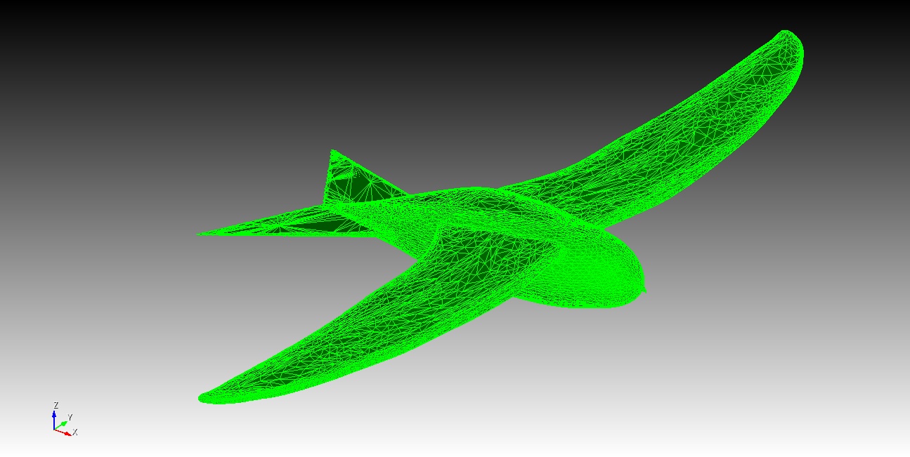
Sorry to restart the conversation on this topic again, but I am beginner in Cubit (shifted from GMSH). I have sculpted my model in Blender and then exporting the model in Cubit as an STL format. Like @Badeli.vahid, i too need to prepare my CFD domain by subtracting the STL geometry from a box. I get the same error. Volume 1 is the STL and Volume 2 is the box.
I import the STL like this. Cubit >> import stl "foo.stl" feature_angle 135.00 merge make_elements
Cubit >> Subtract Volume 1 From Volume 2 Imprint Keep
ERROR: Performing SUBTRACTION with volumes containing geometry
from different modeling engines is not allowed.
Delete uncommon geometry on these volumes before operation.

ERROR: SUBTRACT boolean operation failed
Hi @GauravG91,
have you tried to set the geometry engine to facet before creating the boundary box volume?
This way the volumes should have the same engine.
set geometry engine facet
create brick bounding box Volume 1 extended percentage 50
subtract volume 1 from volume 2
I agree with norbert_hofbauer.
To solve the subtraction issue in Cubit, try setting the geometry engine to facet before creating the bounding box. Use the following commands-
set geometry engine facet
create brick bounding box Volume 1 extended percentage 50
subtract volume 1 from volume 2
This ensures both volumes use the same engine, facilitating the subtraction operation.
I hope it works!
The documentation mentions clearly about the lack of boolean operations for mesh based geometries. Have you worked with blender before ? There the boolean operation is working. So, is it possible to make the domain i.e. a box minus the bird in blender and import it in cubit and then mesh it as a mesh based geometry ?
For meshing, I am following the ITEM method. I saw the youtube tutorial on that following that only.
Hey !
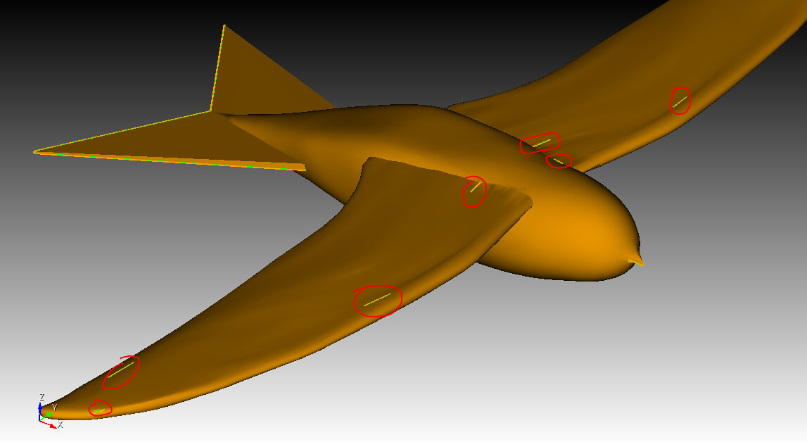
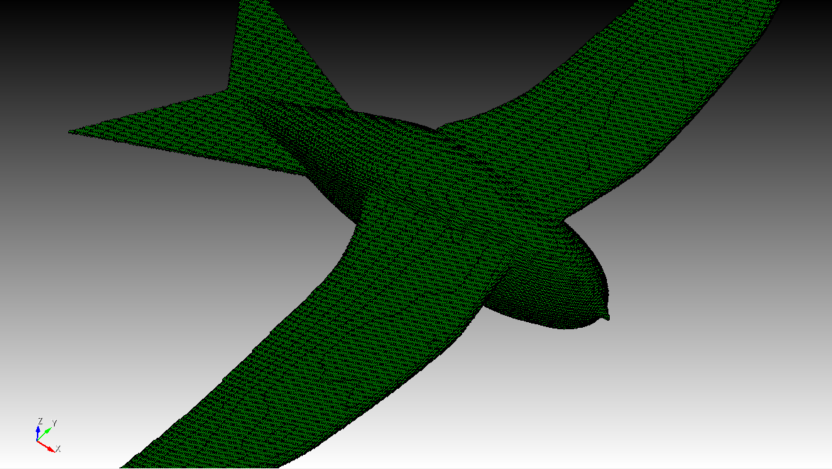
I think the blender to cubit thing is not working. So, I found out another way. I am modelling the organic models in Fusion 360. So, I can import the geometry in .sat format. For example, I modelled this body and imported this in Cubit.
I can do Tet meshing but hex meshing fails. How can I solve this issue ? The submap algorithm fails with the following errors.
Cubit>mesh volume all
Matching intervals successful.
WARNING:  Volume 5 has 2 shells, but scheme submap only supports 1 shell.
ERROR: Volume 5 meshing unsuccessful using scheme: submap
ERROR: 1 volume did not mesh : Volume 5