I have a question related to the processing that can be performed to .step files through Cubit.
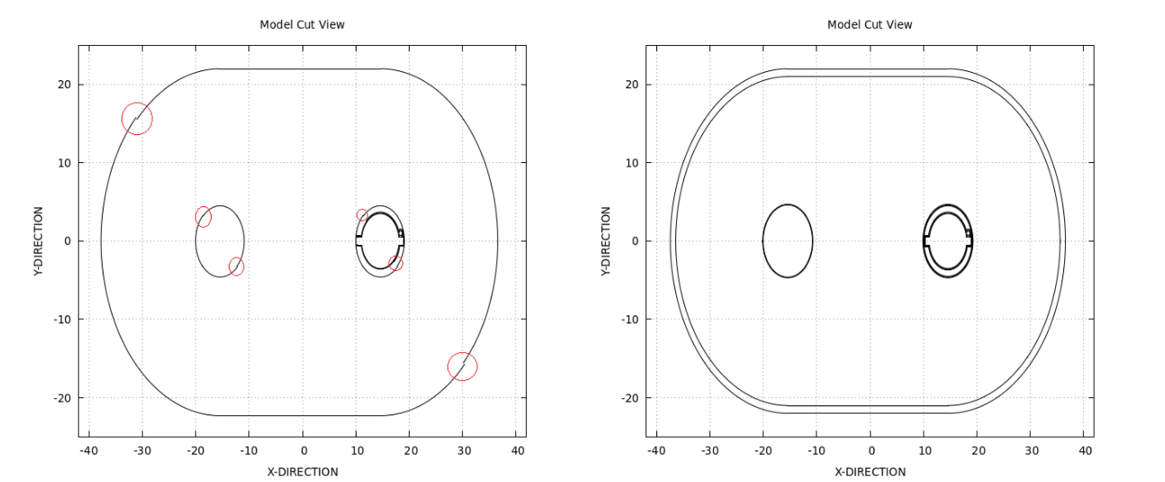
In particular, continuing the discussion of an older topic, I am not sure if the discontinuities in my model XY plane cut section (see attached screenshot)
were eliminated because I reduced the faceting and merge tolerance parameters or because I performed a boolean operation in the 2 exterior volumes of my model in order to separate them.
It is strange because the thickness of the exterior walls of my model is only a few [mm] and the tolerance parameters are several orders of magnitude smaller than this thickness. In the screenshot above it seems that the inner and outer curves of some volumes have been imprinted & merged to a single curve which is discontinuous (notice the circled areas).
Could these discontinuities be justified by the fact that the outer volume (i.e. the ‘cryostat’, see linked topic) is not categorized as a closed volume by cubit, when I imported my .step file?
I’m looking into this. I reduced the faceting to one degree and I still don’t see the discontinuities on the surface. I’m working with Dassault to see if I can determine what is going on during the STEP translation process.
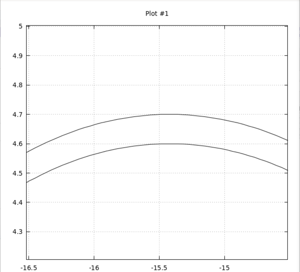
What is the length of the small curves in the discontinuity? The STEP file is using millimeters as the unit and the tolerance is specified as 0.01. If the size is <= 0.01 it will be ignored.
the graph on the left was plotted after exporting the model with cubit as a .h5m file assuming that no overlapping exists between the volumes i.e. I exported the model without separating the volumes (I wanted to notice what difference it would produce):
remove overlap volume 1 8 modify larger
separate body 8
delete Volume 62
imprint volume 1 63
and the faceting & merge tolerance were set equal to 1e-6. At this point I should say that the model was scaled with this command scale 0.1 from [mm] to [cm], so I guess that the tolerance parameter above is also in [cm] after scaling (is that the case?).
The graph on the right hand side was plotted taking into account your recipe for separating the volumes cryostat and dewar and also the tolerances were set equal to 1e-7 for increased detail.
Also to answer your question the thickness of the walls where the discontinuities exist is at the worst case 1[mm] (see screenshots below).
So I concluded that this discontinuity issue was because of the overlapping of the volumes cryostat and dewar, even though at first it looked like the imprint & merge operations where performed with a large tolerance parameter.
I have another question though, how many orders of magnitude lower than the “thinnest gap” in a CAD structure, should the tolerance parameters (for the merge & faceting operations in cubit) be, in order to avoid discontinuities and have the optimal results?
Thank you for the continuous support on this matter,
Nikos.
I was looking at the initial STEP model tolerances and the model as originally imported into Cubit. Do those discontinuities exist in the CAD model? Or, do they seem to be an artifact created by Cubit? Or, is it an artifact of exporting the model to the .h5m file?
Is the .h5m file the MOAB file format? How are you converting from Cubit to .h5m?
The tolerances in Cubit are based on computational limits since there are no units defined by Cubit. If your model is very small < .001 or very large >1e7, we typically recommend scaling into a reasonable numerical space. Too small tends to be a bigger problem because the mesh edge lengths can become numerically unstable with a very dense mesh. Your model seems to be in a reasonable numerical space. The tolerance of 1e-6 should be good down to that limit.
I see a number of sheet bodies were created on importing the STEP file. These are stand-alone surfaces that are not part of any volume. You may want to delete those prior to meshing.
My goal is to import my CAD model to FLUKA and run simulations on it.
I have not located such discontinuities while inspecting the model through cubit’s graphical interface, so they must be a result of processing it through cubit before exporting it to a .h5m format or they could have emerged by processes outside cubit.
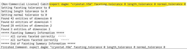
In order to export to .h5m I installed a plugin to cubit for it to perform such conversions, which is part of the DAGMC toolkit (instructions can be found here).
In brief, the commands I used after importing the .step file to Cubit that could have caused this issue are imprint, merge and export dagmc "fliename.h5m" (for the last command the plugin is necessary). It has been verified that the imprint & merge operations are not causing this issue after selecting appropriate tolerance values.
After that, I run a script called make_watertight (more details can be found by following this link) on the exported .h5m file, which aims to seal the triangle facets that meet on the same curve (this is done outside cubit).
To conclude, having sealed my model I run FLUKA simulations and the XY plots attached in my first post are plotted with gnuplot (cut sections of the imported geometry).
@Nikos you might be interested in cad-to-h5m which can automate the conversion of stp files to h5m files and still allow control of faceting and merge tolerance. It also preforms the make_watertight stage
I am revisiting this topic because I would like to get a better picture on which CAD defined solid structures can be successfully meshed using Cubit.
In the .step file that I am attaching to this message, I have isolated a volume which seems not to be automatically meshed by Cubit, i.e. I get a warning of the form:
meshing scheme should be explicitly specified;
volume not automatically mappable, submappable or sweepable.
The default behavior for Cubit is to try to create a hex mesh. Volume 1 is not automatically hex-meshable. Hence, the warning about not mappable, submappable, or sweepable. If you want a tetmesh do
volume all scheme tetmesh prior to issuing any mesh commands.
The volume in this model is a thin shell so the mesh quality will be very dependent on the element size. Also, there are extra “sheet bodies” in the model. You may want to delete those extra surfaces before trying to mesh.
@Nikos your original issue may well stem from improperly imprinted and merged geometry, it looks like your plotting FluDAG geometries using the native plotter, it relies upon using DAGMC to trace through the geometry to produce these images, so if you’re seeing and aberation as you did originally, it could well be to do with that. The DAGMC process relies upon the graphics facets as produced by Cubit, so meshing here wouldnt help.
I will try to briefly put into perspective the problem I am facing.
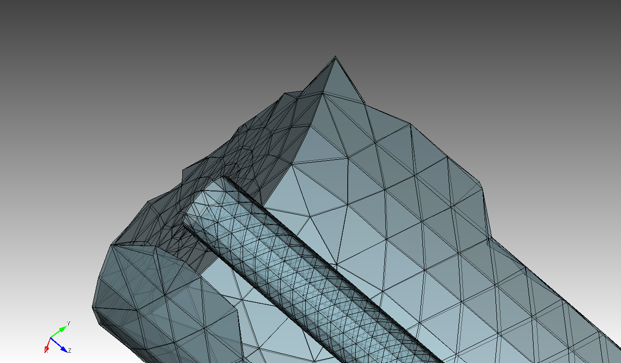
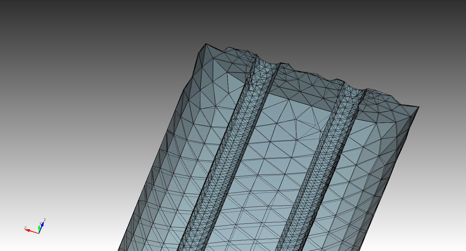
I have a volume called ‘cryostat’ (later during the FLUKA simulations it is made out of IRON) which is properly meshed by cubit preserving the interior cylinder thickness to 1mm and the exterior thickness to 3mm (more intuitively the cryostat can be described as a thin “shell”, attaching screenshots below)
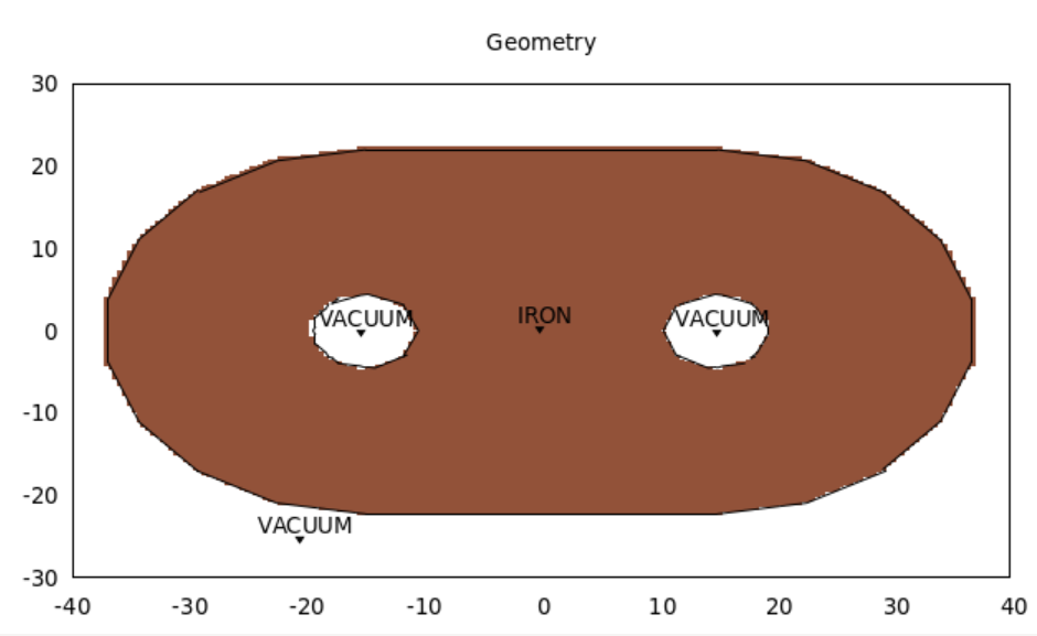
but instead the geometry I see when I plot using Gnuplot looks like this (the interior of the outer surface boundary should not be made out of IRON, only a thin wall of 3mm thickness in the outer boundary and a 1mm thick wall of the inner cylinders should correspond to the IRON material):
this is how I am expecting the imported CAD geometry, of the “crysotat” to FLUKA, to look like (this plot was produced after performing some boolean operations between neighboring volumes with cubit):
@makeclean, would it help the DAGMC processing if @Nikos modified the graphics facet tolerance? He has some very thin volumes. Try graphics tolerance angle 3. The default is 15 degrees which is good enough for most visualization and doesn’t create too many facets which slows down the processing. I do know people that set the tolerance angle down to 1 degree. That will have an impact on performance in some operations.
Hi @Nikos I think there are a bunch of things happening here.
You’ve got tet-mesh and regular geometry going on at the same time, unless you have a use for the tet-mesh for something else, you can go ahead and delete it, its of no use in the FluDAG calculation.
It looks to me like you’ve solved your own problem, the last plot you attached looks correct to me.
In terms of faceting, using the dagmc exporter I would use faceting_tolerance 1e-4 as your argument, that should generate your facets with sufficient accuracy.
@karl you would be right, but we call the faceter seperately during the DAGMC export.