Hi @REardleyBrunt and @strieben,
sorry for the delay, it took some time to write a script for this.
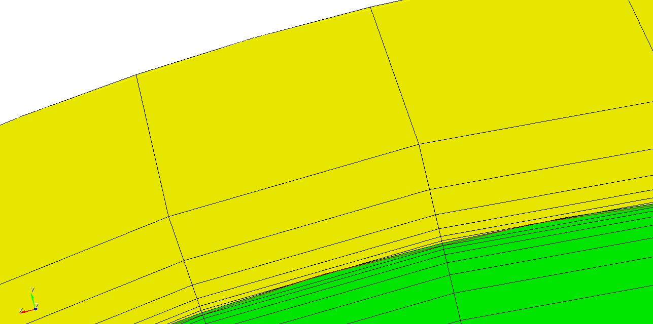
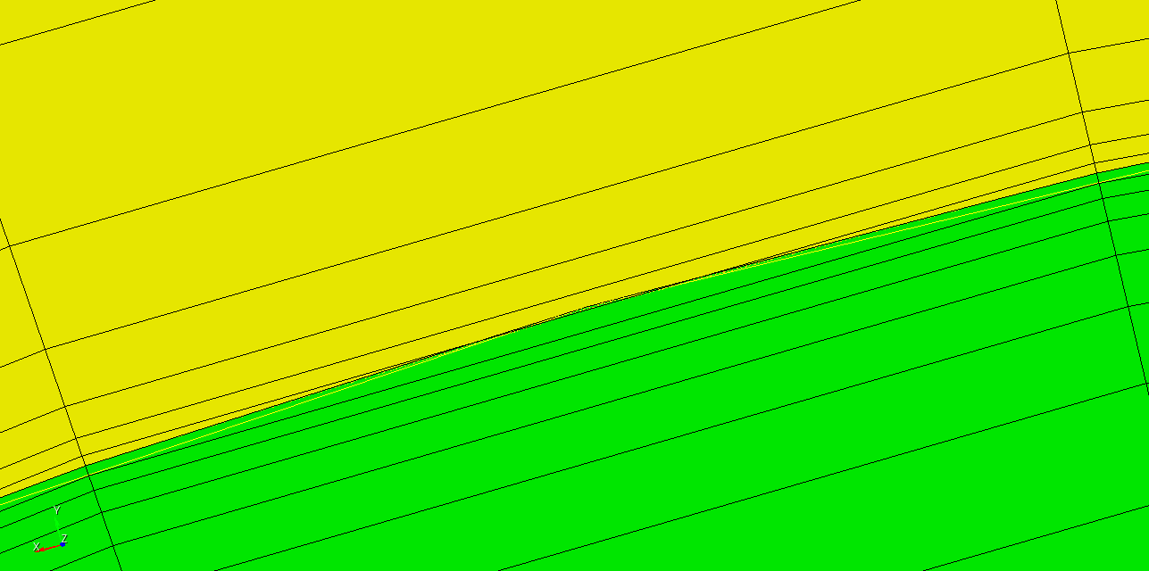
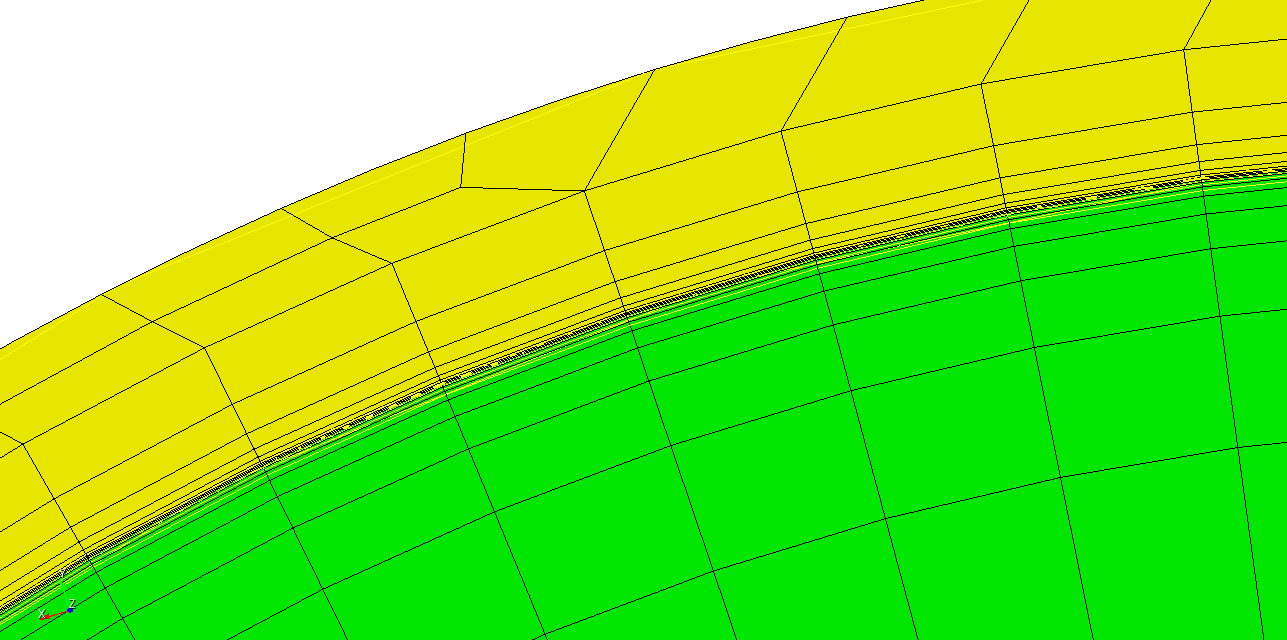
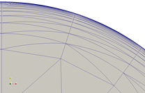
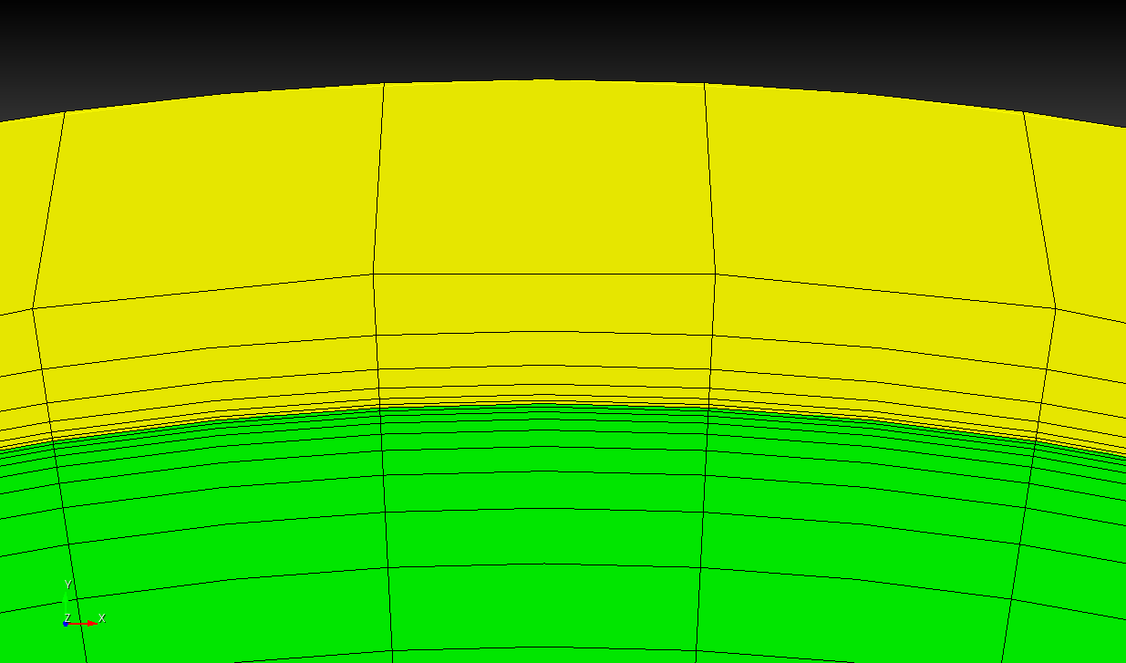
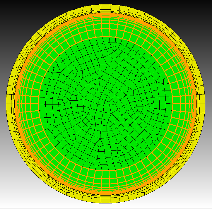
First of all a screenshot to show you that it’s possible to place the midnodes.
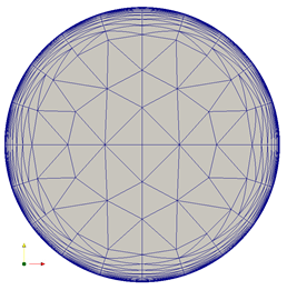
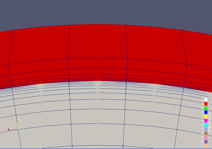
and the same just in paraview
So a short explanation how this can be done. I started with your example script from above.
Then i choose the volume and the boundary surface for which i want the adjust the hex nodes.
To get my wanted hexes near the boundary i can define a distance. The distance is used to check if the center point from a hex is near enough to the surface.
volume_id = 1
surface_id = 1
distance = 2.5e-1
hex_ids = get_elements(volume_id,surface_id,distance)
The get_elements checks the distance from the hexes and put them into a list if they are in range.
With the above values i can get the hexes that are within the boundary layer for volume 1.
When i got the hexes we can already process them. I turn off some output to speed things up. Otherwise the command line output will slow us down greatly.
cubit.cmd(f"info off")
cubit.cmd(f"warning off")
cubit.cmd(f"graphics off")
adjust_elements(hex_ids,surface_id,volume_id)
cubit.cmd(f"info on")
cubit.cmd(f"warning on")
cubit.cmd(f"graphics on")
The adjust_elements loops over all hexes. It computes the side of the hex that’s nearest to the surface and the average distance of the nodes in the vertices from that side. This average distance will be used to move the midnodes to the same distance to the surface. Only the nearest side of the hex will be adjusted, not the opposite side too.
def adjust_elements(hex_ids,surface_id,volume_id):
cubit.cmd("set node constraint off")
#check if hex20
if (len(hex_ids) > 0):
conn = cubit.get_expanded_connectivity("hex",hex_ids[0])
if not (len(conn)==20):
print("Not HEX20!")
return False
#get surface
surface = cubit.surface(surface_id)
#loop over hexes
max_hexes = len(hex_ids)
current_hex = 0
counter = 0
for hid in hex_ids:
conn = cubit.get_expanded_connectivity("hex",hid)
#adjust side
side,distance = get_side_and_distance(conn,surface)
adjust_side_distance(side,distance,conn,surface,volume_id)
current_hex = current_hex + 1
counter = counter + 1
if counter==500:
cubit.cmd(f"info on")
print(f"adjusted {current_hex} hexes from {max_hexes} for volume {volume_id} and surface {surface_id}")
counter = 0
cubit.cmd(f"info off")
Here is the complete journal. Hopefully that’s what you were looking for. Also please note that’s it’s only working for hex20.
#!python
cubit.cmd("reset")
import sys
sys.path.append('/opt/Coreform-Cubit-2023.11/bin')
import cubit

### User Settings ###

L_r_fluid = 1           # pipe interior radius
L_r_solid = 1.1         # pipe exterior radius
L_z = 5                 # pipe length

delta_z_axial = 1e-1
delta_xy_core = 1e-1
fluid_first_row = 1e-3
fluid_growth_factor = 1.5
fluid_num_layers = 12
solid_first_row = 1e-3
solid_growth_factor = 1.8
solid_num_layers = 6

### Generate Geometry ###

cubit.cmd(f'cylinder height {L_z} radius {L_r_fluid}') # fluid region
cubit.cmd(f'cylinder height {L_z} radius {L_r_solid}') # solid+fluid region
cubit.cmd('subtract volume 1 from volume 2 keep_tool') # create solid-only region

# Imprint and merge
cubit.cmd('imprint volume all')
cubit.cmd('merge volume all')
cubit.cmd('compress')

### Set up boundary layers ###

# Create boundary layer in fluid region
cubit.cmd('create boundary_layer 1')
cubit.cmd(f'modify boundary_layer 1 uniform height {fluid_first_row} growth {fluid_growth_factor} layers {fluid_num_layers}')
cubit.cmd('modify boundary_layer 1 add surface 1 volume 1')
cubit.cmd('modify boundary_layer 1 continuity off')

# Create boundary layer in solid region
cubit.cmd('create boundary_layer 2')
cubit.cmd(f'modify boundary_layer 2 uniform height {solid_first_row} growth {solid_growth_factor} layers {solid_num_layers}')
cubit.cmd('modify boundary_layer 2 add surface 1 volume 2')
cubit.cmd('modify boundary_layer 2 continuity off')

### Generate Mesh ###

# create element blocks
cubit.cmd('block 1 add volume 1')
cubit.cmd('block 2 add volume 2')

# set element type
cubit.cmd('block 1 element type hex20')
cubit.cmd('block 2 element type hex20')

# force nodes to follow curved surfaces
cubit.cmd('set node constraint on')

# Set mesh size for axial resolution (on all volumes)
cubit.cmd(f'volume 1 2 size {delta_z_axial}')

# Set approximate mesh size for core (on fluid & solid inlet surfaces)

cubit.cmd(f'surface 2 5 size {delta_xy_core}')

# Mesh fluid inlet

cubit.cmd('surface 2 scheme pave')
cubit.cmd('mesh surface 2')

# Mesh solid inlet

cubit.cmd('surface 5 scheme pave')
cubit.cmd('mesh surface 5')

# Sweep mesh through volume

cubit.cmd('volume 1 2 redistribute nodes off')
cubit.cmd('volume 1 scheme Sweep source surface 2 target surface 3 sweep transform least squares')
cubit.cmd('volume 2 scheme Sweep source surface 5 target surface 6 sweep transform least squares')
cubit.cmd('volume 1 2 autosmooth target on fixed imprints off smart smooth off')
cubit.cmd('mesh volume 1')
cubit.cmd('mesh volume 2')
import numpy
# get all elements from a volume wich are in range from the surface
def get_elements(volume_id,surface_id,distance):
#hex_ids = cubit.parse_cubit_list( "hex", f"all in volume {volume_id} with z_coord>2.4" )
hex_ids = cubit.parse_cubit_list( "hex", f"all in volume {volume_id}" )
surface = cubit.surface(surface_id)
return_hex_ids=[]
for hid in hex_ids:
location = numpy.array(cubit.get_center_point("hex",hid))
new_location = numpy.array(surface.closest_point_trimmed(location))
delta = new_location - location
current_distance = numpy.linalg.norm(delta)
if current_distance<=distance:
return_hex_ids.append(hid)
#print(f"volume {volume_id} surface {surface_id} distance {distance}")
return return_hex_ids
#calc hex vertice distance to surface per side
def get_side_distance(side,connectivity,surface):
distance = 0
node_ids=[]
if side == 1:
node_ids.append(connectivity[0])
node_ids.append(connectivity[1])
node_ids.append(connectivity[4])
node_ids.append(connectivity[5])
elif side == 2:
node_ids.append(connectivity[1])
node_ids.append(connectivity[2])
node_ids.append(connectivity[5])
node_ids.append(connectivity[6])
elif side == 3:
node_ids.append(connectivity[2])
node_ids.append(connectivity[3])
node_ids.append(connectivity[6])
node_ids.append(connectivity[7])
elif side == 4:
node_ids.append(connectivity[0])
node_ids.append(connectivity[3])
node_ids.append(connectivity[4])
node_ids.append(connectivity[7])
elif side == 5:
node_ids.append(connectivity[0])
node_ids.append(connectivity[1])
node_ids.append(connectivity[2])
node_ids.append(connectivity[3])
elif side == 6:
node_ids.append(connectivity[4])
node_ids.append(connectivity[5])
node_ids.append(connectivity[6])
node_ids.append(connectivity[7])
for nid in node_ids:
location = numpy.array(cubit.get_nodal_coordinates(nid))
new_location = numpy.array( surface.closest_point_trimmed(location) )
delta = new_location - location
current_distance = numpy.linalg.norm(delta)
distance = distance + current_distance
distance = distance/4
return distance
#get side number that's facing the surface
def get_side_and_distance(connectivity,surface):
distance = []
distance.append(get_side_distance(1,connectivity,surface))
distance.append(get_side_distance(2,connectivity,surface))
distance.append(get_side_distance(3,connectivity,surface))
distance.append(get_side_distance(4,connectivity,surface))
distance.append(get_side_distance(5,connectivity,surface))
distance.append(get_side_distance(6,connectivity,surface))
side = distance.index(min(distance))+1
return side,min(distance)
#calc adjust middle nodes distance to surface per side
def adjust_side_distance(side,distance,connectivity,surface,volume_id):
node_ids=[]
if side == 1:
node_ids.append(connectivity[8])
node_ids.append(connectivity[12])
node_ids.append(connectivity[13])
node_ids.append(connectivity[16])
elif side == 2:
node_ids.append(connectivity[9])
node_ids.append(connectivity[13])
node_ids.append(connectivity[14])
node_ids.append(connectivity[17])
elif side == 3:
node_ids.append(connectivity[10])
node_ids.append(connectivity[14])
node_ids.append(connectivity[15])
node_ids.append(connectivity[18])
elif side == 4:
node_ids.append(connectivity[11])
node_ids.append(connectivity[12])
node_ids.append(connectivity[15])
node_ids.append(connectivity[19])
elif side == 5:
node_ids.append(connectivity[8])
node_ids.append(connectivity[9])
node_ids.append(connectivity[10])
node_ids.append(connectivity[11])
elif side == 6:
node_ids.append(connectivity[16])
node_ids.append(connectivity[17])
node_ids.append(connectivity[18])
node_ids.append(connectivity[19])
for nid in node_ids:
skip = False
location = numpy.array(cubit.get_nodal_coordinates(nid))
new_location = numpy.array(surface.closest_point_trimmed(location))
current_delta = new_location - location
if distance > 0:
if not ((current_delta[0]==0) and (current_delta[0]==0) and (current_delta[0]==0)):
unit_delta = current_delta / numpy.linalg.norm(current_delta)
contained = cubit.is_point_contained("volume",volume_id,location)
if (contained==1) or (contained==2):
delta = current_delta - unit_delta*distance
elif contained==0:
delta = current_delta + unit_delta*distance
print(f"node_id {nid} distance {distance} unit_delta {unit_delta}")
print(f"current_delta {current_delta} delta {delta}")
else:
skip = True
else:
delta = current_delta
if not skip:
cubit.cmd( f"node {nid} move x {delta[0]} y {delta[1]} z {delta[2]}")
return True
# move middle nodes from hex20 to align to a surface
def adjust_elements(hex_ids,surface_id,volume_id):
cubit.cmd("set node constraint off")
#check if hex20
if (len(hex_ids) > 0):
conn = cubit.get_expanded_connectivity("hex",hex_ids[0])
if not (len(conn)==20):
print("Not HEX20!")
return False
#get surface
surface = cubit.surface(surface_id)
#loop over hexes
max_hexes = len(hex_ids)
current_hex = 0
counter = 0
for hid in hex_ids:
conn = cubit.get_expanded_connectivity("hex",hid)
#adjust side
side,distance = get_side_and_distance(conn,surface)
adjust_side_distance(side,distance,conn,surface,volume_id)
current_hex = current_hex + 1
counter = counter + 1
if counter==500:
cubit.cmd(f"info on")
print(f"adjusted {current_hex} hexes from {max_hexes} for volume {volume_id} and surface {surface_id}")
counter = 0
cubit.cmd(f"info off")
return True
volume_id = 1
surface_id = 1
distance = 2.5e-1
hex_ids = get_elements(volume_id,surface_id,distance)
cubit.cmd(f"info off")
cubit.cmd(f"warning off")
cubit.cmd(f"graphics off")
adjust_elements(hex_ids,surface_id,volume_id)
cubit.cmd(f"info on")
cubit.cmd(f"warning on")
cubit.cmd(f"graphics on")
#cubit.cmd(f"select hex {' '.join(str(hid) for hid in hex_ids)}")
volume_id = 2
surface_id = 1
distance = 5e-2
hex_ids = get_elements(volume_id,surface_id,distance)
cubit.cmd(f"info off")
cubit.cmd(f"warning off")
cubit.cmd(f"graphics off")
adjust_elements(hex_ids,surface_id,volume_id)
cubit.cmd(f"info on")
cubit.cmd(f"warning on")
cubit.cmd(f"graphics on")
#cubit.cmd(f"select hex {' '.join(str(hid) for hid in hex_ids)}")
#cubit.cmd(f"export mesh 'smoothed_boundary.e' overwrite")
