Hi,
I use sheet bodies for the generation of internal surfaces in a volume, do compute, for example, the magnetic flux. In doing so, I recognize, that the extracted sheet body from another body don’t get merged, which means, when I do “highlight surfaces not is_merged”, this surface is shown. Furthermore, when I compare the computed magnetic flux and the analytic solution, a deviation in the results can be observed. When I use a another approach by defining a volume and subtract this volume form another one to generate a surface for the magnetic flux computation, the result fits with the analytic one. Using webcuts would also work for this example, but for a more complex example, this becomes very cumbersome.
My question is, how are sheet bodies working and is my approach for generating internal surfaces with sheet bodies feasible?
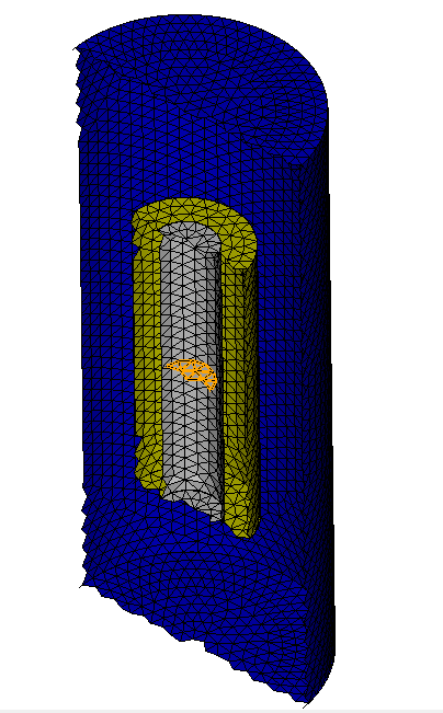
I also add different variation for the generation of internal surfaces. The testcase is a coil with an iron core surrounded with air. In the middle of the iron core I want to create the internal surface.
For “test_magFlux_V1.jou” to “test_magFlux_V3.jou” I use sheet bodies and in “test_magFlux_V4.jou” I use a volume. For V1 to V3 the results are wrong and for V4 the results of the computation fits with the analytic one.
Looking at the version 1 file, I don’t see any sheet bodies. I do see the following:
create Cylinder height 1 radius 4
move volume 2 z -0.5
subtract volume 5 from volume 1 keep_tool
Is there a typo here? Did you mean to move volume 5 that was just created? If you want to move volume 2 you should move it before you do the Boolean operation so that the surfaces will align after the Boolean operation.
I am not a magnetics simulation expert, but it does seem odd to me that you are applying a boundary condition called “S_flux” on nodes. Typically, a flux is defined over an area. Thus, you would define the boundary condition on element faces using a sideset.
thanks for the answer.
Ok, thats interesting, because the file should look like
reset

create Cylinder height 50 radius 5
create Cylinder height 50 radius 10

subtract volume 1 from volume 2 keep_tool
create surface circle radius 4 zplane

create Cylinder height 100 radius 20
subtract volume 1 2 from volume 4 keep_tool

subtract body 3 from body 1 imprint

imprint all
merge all

volume all tetmesh growth_factor 1.1
volume all scheme tetmesh
volume all size 2
mesh volume all

block 1 add volume 6
block 1 name "V_core"

block 2 add volume 2
block 2 name "V_coil"

block 3 add volume 5
block 3 name "V_air"

nodeset 1 add surface not is_merged except surface 17
nodeset 1 name "BC_outer"

nodeset 2 add surface 17
nodeset 2 name "S_flux"

body all scale 0.001

export ansys cdb "test_magFlux.cdb" overwrite
The sheet surface is created with
create surface circle radius 4 zplane
which is then subtract from body 1.
You are absolutely right, but with our FEM-Solver, we have to load a cdb-File and as far as I know sidesets are not written out, only blocks and nodesets.
Hi Karl,
when I understand it correctly, you don’t subtract the sheet body from the core volume and then used the meshing strategy shown above?
In doing so, the mesh looks valid. However, when I “highlight surface not is_merged”, the nodes in this surface aren’t merged. I assume, this is the issue in the simulation. Is it somehow possible to force the merging of this surface?
That is correct. With the tetmesh respect option you don’t have to create the non-manifold geometry. It gets added directly into the mesh.
The surface is not merged, but the nodes are merged. If I do a coincident node check,
topology check coincident node volume all tolerance .5 draw brief result group
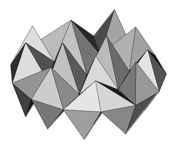
it shows that all there are no nodes in the volumes closer than .5 units. The image above with the tetrahedra on the circle shows that the nodes are connected to the tetrahedra on both sides. Similarly,
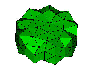
doing a draw tet in node in nodeset 2 shows that the tets are correctly attached to the flux source.
I’m not sure where the disconnect between the mesh and the analysis is occurring. I believe that the mesh is correct.