Thanks again to everyone who attended today’s webinar (“AI-Driven FEA Preprocessing: Using Coreform Cubit’s New RPC Interface” – Sept 11, 2026)!
Especially given that there was a slight hiccup in today’s webinar, due to my failure to copy the intended hex-mesh & journal file from the working directory to the clean directory I was working in during the webinar, I thought I’d make this post and share as much as I can. My hope is that this might help you better understand the capabilities of the new RPC interface & of a frontier LLM model & harness.
Geometry:
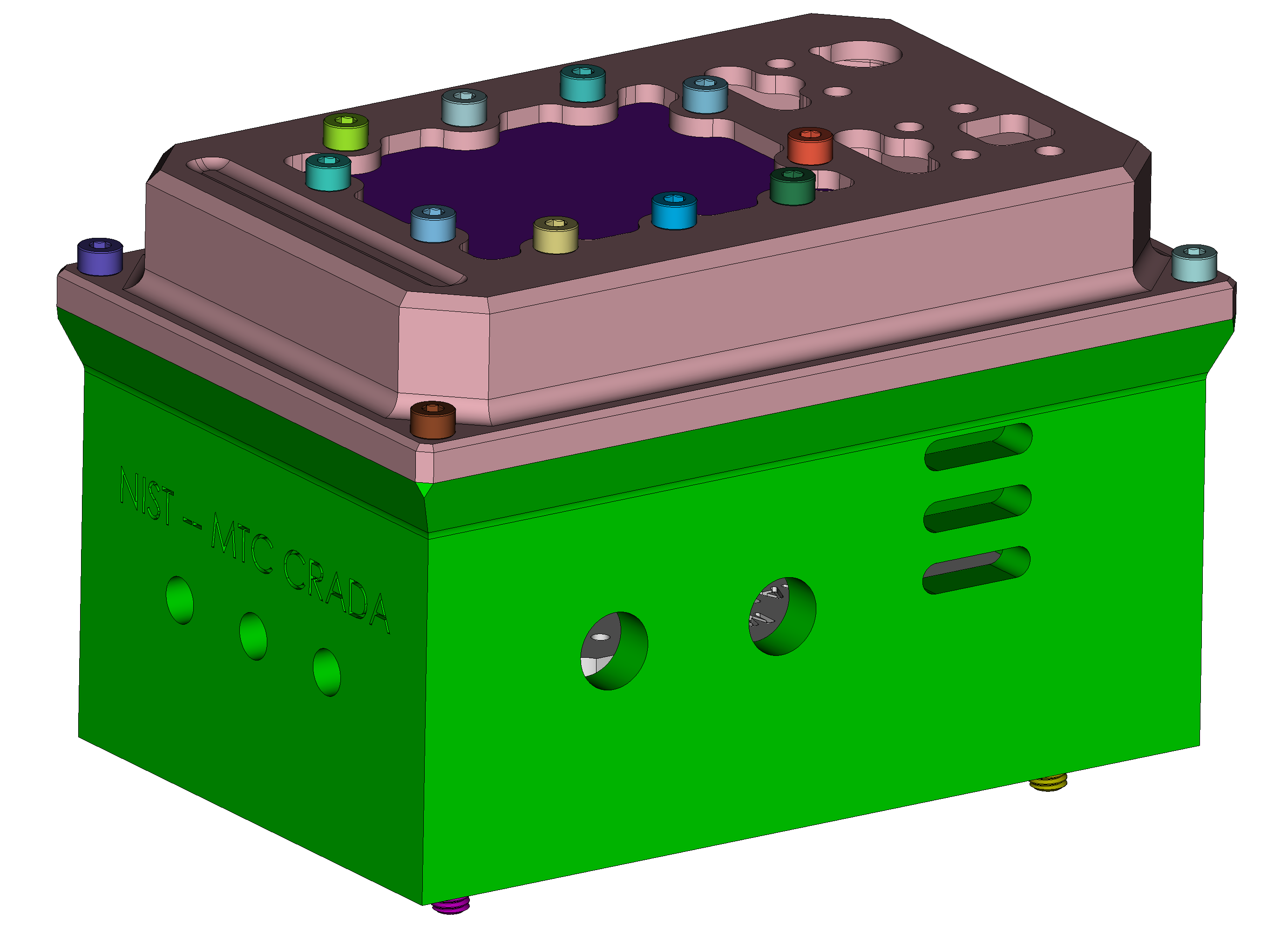
This is the geometry I used for the experiment. This is an ACIS file that I derived from NIST’s “MBE PMI Validation and Conformance Testing Project”. I downloaded the CAD models from this direct-download link: https://www.nist.gov/document/nist-cad-models-mtc-assembly, and converted the contained SolidWorks assembly to an ACIS .sat file so that no SolidWorks import license is required for users to load the model. I’ve uploaded that ACIS file to this post, download link is below:
nist_mtc_crada_assembly_rev-D.sat (8.4 MB)
LLM & Harness information
- IDE: VS Code
- Harness: OpenAI Codex (via OpenAI’s official VS Code Extension)
- Model: GPT-6 Astra (with
Extra Highthinking)
Prompting & Workflow
There was a bit of pre-prompting I did to try to steer Codex away from previous Skills that I’d made, or previous attempts from Claude Fable. I worked in a clean directory, but wanted to make sure that Codex wouldn’t “go snooping around” for the answer in some other directory.
My initial prompt is below.
Note 1: I’ve replaced my actual paths with <path-to-cad-file> for brevity.
Note 2: I used /goal mode for this prompt, I did not use it for any follow-up prompts.
I have a CAD file at
<path-to-cad-file>/nist_mtc_crada_assembly_rev-D.satthat is an assembly including bolts. I intend to run an explicit dynamics drop test on this assembly and would like your assistance preparing this model i.e., help me build a Coreform Cubit journal file.
- I’d like your assistance in identifying bolts and replacing them with “spider elements” (sometimes called connector elements). Because this drop test won’t include the next-level assembly that this assembly is usually mounted onto, the four bolts on the bottom of the housing can be removed altogether.
- I’d like your help in defeaturing this model to prepare for hex-meshing for the drop-test simulation. The model’s units are
mmand it consists of a SS-304L housing & cover, a plexiglass window, and an FR4 PCB. We should aim for a stable time-step of ~1e-8 seconds minimum and ideally ~1e-7 - that should help drive your goals regarding drop test meshing.- The drop test will consist of the assembly dropping from a six-foot height onto its base (z-min) - and a series of simulations with the angle being slightly perturbed (so that one case will be hitting exactly all four feet at the same time and others wiill be slightly different angles)
- The principle concerns are damage to the circuit board and secondarily, to the plexiglass window
- Make sure to make all set assignments so I can run this.
- Other than the mesh you (hopefully!) produce, your main output from this work should be a Coreform Cubit journal file that I can run, or potentially “pick up” and finish - so please make sure it’s clean and robust!
I want to watch you work, so please use the interactive session I’ve launched as much as you are able.
Codex then asked two follow-up questions, to which I responded (bullet points):
- Which solver will run the drop test? This determines how I should represent the bolt spiders, contact, and analysis sets.
- I responded with
Sierra/SM- a US Gov’t solver developed by Sandia National Labs, as I have a lot of experience with that tool (this solver is not available for use outside of official US Gov’t work)- Do you have PCB stackup/component masses, bolt preload values, or calibrated material/damage cards to include? I’ll keep preparing the CAD and sets; without those, the handoff will distinguish the mesh and contact setup from the material assumptions still needed for damage prediction.
- No - for now just assume its solid FR4.
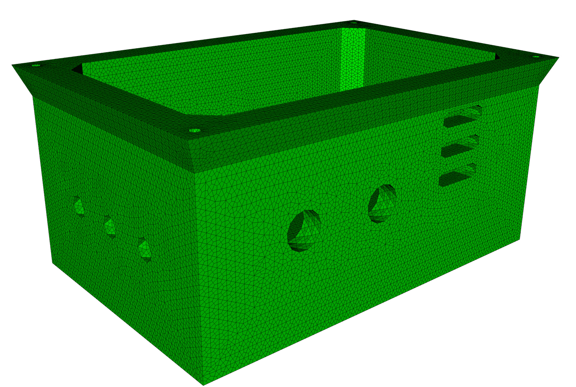
As I watched it work, I noticed that it tried various methods of trying to mesh the bottom housing. It tried Coreform Cubit Sculpt, which it discarded, and it discovered our “THex” scheme that converts each tet-element of a tet-mesh into four hex elements:
So I “steered” Codex mid-stream:
The
thexapproach may result in very poor quality elements - if you need to do tied constraints between incompatible regions, and are confident that the tied constraints won’t adversely affect the desired results, you could try that. Thethexapproach might be useful though, so maybe don’t throw it away (e.g., maybe two different journal files? Anifstatement?)
After ~1.5 hours Codex completed:
I preserved both approaches as separate journals:
- [THex baseline](prepare_drop_test_thex.jou)
- [Swept/tied alternative](prepare_drop_test_swept_tied.jou)
Metric THex Swept/tied Solid hexes 442,914 86,339 Minimum scaled Jacobian 0.107 0.158 Hexes below 0.2 57 16 Geometric time-step screen 1.33e-8 s 2.80e-8 s
Both replay from the original SAT with zero Cubit errors. The alternative’s three housing interfaces pass coverage and kinematic checks for all 3,859 tied nodes, without bolt-spider conflicts. It is currently displayed in Cubit.
Sierra has not been run, so I cannot yet confirm that the ties leave PCB/window response unaffected. The time-step figures are mesh screens, not solver results.
[Handoff and comparison details](README.md) include the remaining quality limitations, contact assumptions, and matching Sierra cases.
This was the state that I shared during the webinar. Here are the two journal files that it created (note: that I’m again inserting <path-to-file> in place of my actual paths, so if you want to run these journal files yourself, you’ll need to replace those).
prepare_drop_test_thex.jou
# NIST MTC CRADA rev-D: drop-test preparation for Sierra/SM.
# Units: mm. This journal RESETS the current Cubit model.
# Full geometry, solid mesh, connector, analysis-set, and Exodus preparation.
# Run build_journal.py after moving this folder to regenerate absolute paths.
# Source: <path-to-file>/nist_mtc_crada_assembly_rev-D.sat
reset
import acis '<path-to-file>/nist_mtc_crada_assembly_rev-D.sat'

# ---- 01_remove_hardware.jou ----
# Classifier and geometric inspection: bottom mounting bolts 2:5 have no mating assembly.
# PCB bolts 7:10, cover bolts 13:16, window bolts 17:26, window nuts 27:36.
# Retained joints will be replaced after the attachment surfaces are cleaned.
delete volume 2 to 5 7 to 10 13 to 36
volume 1 name 'housing_ss304l'
volume 11 name 'cover_ss304l'
volume 12 name 'window_pmma'
volume 6 name 'pcb_fr4'
block 1 volume 1
block 1 name 'housing_ss304l'
block 2 volume 11
block 2 name 'cover_ss304l'
block 3 volume 12
block 3 name 'window_pmma'
block 4 volume 6
block 4 name 'pcb_fr4'
color volume 1 lightblue
color volume 11 grey
color volume 12 cyan
color volume 6 green
view iso
graphics reset

# ---- 02_remove_markings.jou ----
# Remove recessed lettering and enclosed letter islands; preserve functional cutouts.
remove surface 250 to 408 extend
remove surface 571 to 767 extend
remove surface 1037 to 1205 extend
# Idealize four PCB countersinks to straight clearance holes for swept hex meshing.
# Connector coupling will represent the bearing/load-transfer region.
remove surface 516 518 520 522 extend
# Shallow cover slot: cosmetic/non-attachment pocket, remove walls and floor together.
remove surface 918 985 to 992 extend
graphics reset
view iso

# ---- 03_simplify_housing.jou ----
# The CAD contains no gasket solid. Fill the narrow sealing groove on the mating rim.
remove surface 2 to 8 26 to 42 198 to 245 extend
# Flatten drill-tip cones in tapped PCB and lid holes; retain bore locations/depths.
tweak surface 46 48 50 52 84 86 88 90 cone
# Remove interior floor/boss blend networks, leaving the load-bearing walls and shelves.
remove surface 115 to 181 extend

# ---- 04_simplify_cover.jou ----
# Remove cover wall/roof and flange blend networks for an explicit sweep decomposition.
remove surface 993 to 1016 extend
remove surface 943 to 950 extend
# Remove the 2 mm top perimeter chamfer and 1 mm flange edge chamfer.
remove surface 1021 to 1036 extend

# ---- 05_mesh_panels.jou ----
# Swept HEX8 panels: PCB 4 layers; window 3 layers.
volume 6 size 1.5
surface 509 scheme pave
curve 1424 interval 4
curve 1425 interval 4
curve 1426 interval 4
curve 1427 interval 4
curve 1428 interval 4
curve 1429 interval 4
curve 1430 interval 4
curve 1431 interval 4
curve 1436 interval 4
curve 1437 interval 4
curve 1438 interval 4
curve 1439 interval 4
curve 1440 interval 4
curve 1441 interval 4
curve 1442 interval 4
curve 1443 interval 4
curve 1444 interval 4
curve 1445 interval 4
curve 1446 interval 4
curve 1447 interval 4
curve 1448 interval 4
curve 1449 interval 4
curve 1450 interval 4
curve 1451 interval 4
curve 1452 interval 4
curve 1453 interval 4
curve 1454 interval 4
curve 1455 interval 4
curve 1456 interval 4
curve 1457 interval 4
curve 1458 interval 4
curve 1459 interval 4
curve 1460 interval 4
curve 1461 interval 4
curve 1462 interval 4
curve 1463 interval 4
curve 1464 interval 4
curve 1465 interval 4
curve 1466 interval 4
curve 1467 interval 4
volume 6 scheme sweep source surface 509 target surface 510
mesh volume 6
volume 12 size 1.5
surface 1210 scheme pave
curve 2919 interval 3
curve 2921 interval 3
curve 2923 interval 3
curve 2926 interval 3
volume 12 scheme sweep source surface 1210 target surface 1211
mesh volume 12

# ---- 06_cover_hex.jou ----
# Sweep the cover as flange, wall, and roof; preserve separate contact parts.
remove surface 1017 to 1020 extend
webcut volume 11 with plane zplane offset 76
webcut volume 11 with plane zplane offset 92.05
block 2 add volume 45 46
imprint volume 11 45 46
merge volume 11 45 46
volume 11 45 46 size 1.5
volume 11 45 46 scheme auto
mesh volume 11 45 46

# ---- 07_housing_thex.jou ----
# Conforming unstructured housing hexes: tetrahedral seed, four hexes per tet.
# Preserve the curved foot transitions, mounting holes, and side apertures.
remove surface 111 to 114 246 to 249 extend
volume 1 size 3.0
volume 1 scheme tetmesh geometry approximation angle 30
mesh volume 1
# Linear subdivision avoids inversion/short edges from projecting newly inserted
# subdivision nodes onto curved CAD. Housing boundary follows the seed triangles.
set node constraint off
thex volume 1
set node constraint on
block 1 element type hex8

save cub5 '<path-to-file>/07_final_solids.cub5' overwrite
playback '<path-to-file>/configure_paths.py'
playback '<path-to-file>/audit_solids.py'
playback '<path-to-file>/make_connections_sets.py'

graphics reset
view iso
prepare_drop_test_swept_tied.jou
# Swept housing with three internal tied interfaces for Sierra/SM.
# This journal RESETS the current model. See swept_tied_variant/README.md.
reset
import acis '<path-to-file>/nist_mtc_crada_assembly_rev-D.sat'

# 01_remove_hardware.jou
# Classifier and geometric inspection: bottom mounting bolts 2:5 have no mating assembly.
# PCB bolts 7:10, cover bolts 13:16, window bolts 17:26, window nuts 27:36.
# Retained joints will be replaced after the attachment surfaces are cleaned.
delete volume 2 to 5 7 to 10 13 to 36
volume 1 name 'housing_ss304l'
volume 11 name 'cover_ss304l'
volume 12 name 'window_pmma'
volume 6 name 'pcb_fr4'
block 1 volume 1
block 1 name 'housing_ss304l'
block 2 volume 11
block 2 name 'cover_ss304l'
block 3 volume 12
block 3 name 'window_pmma'
block 4 volume 6
block 4 name 'pcb_fr4'
color volume 1 lightblue
color volume 11 grey
color volume 12 cyan
color volume 6 green
view iso
graphics reset

# 02_remove_markings.jou
# Remove recessed lettering and enclosed letter islands; preserve functional cutouts.
remove surface 250 to 408 extend
remove surface 571 to 767 extend
remove surface 1037 to 1205 extend
# Idealize four PCB countersinks to straight clearance holes for swept hex meshing.
# Connector coupling will represent the bearing/load-transfer region.
remove surface 516 518 520 522 extend
# Shallow cover slot: cosmetic/non-attachment pocket, remove walls and floor together.
remove surface 918 985 to 992 extend
graphics reset
view iso

# 03_simplify_housing.jou
# The CAD contains no gasket solid. Fill the narrow sealing groove on the mating rim.
remove surface 2 to 8 26 to 42 198 to 245 extend
# Flatten drill-tip cones in tapped PCB and lid holes; retain bore locations/depths.
tweak surface 46 48 50 52 84 86 88 90 cone
# Remove interior floor/boss blend networks, leaving the load-bearing walls and shelves.
remove surface 115 to 181 extend

# 04_simplify_cover.jou
# Remove cover wall/roof and flange blend networks for an explicit sweep decomposition.
remove surface 993 to 1016 extend
remove surface 943 to 950 extend
# Remove the 2 mm top perimeter chamfer and 1 mm flange edge chamfer.
remove surface 1021 to 1036 extend

# 05_mesh_panels.jou
# Swept HEX8 panels: PCB 4 layers; window 3 layers.
volume 6 size 1.5
surface 509 scheme pave
curve 1424 interval 4
curve 1425 interval 4
curve 1426 interval 4
curve 1427 interval 4
curve 1428 interval 4
curve 1429 interval 4
curve 1430 interval 4
curve 1431 interval 4
curve 1436 interval 4
curve 1437 interval 4
curve 1438 interval 4
curve 1439 interval 4
curve 1440 interval 4
curve 1441 interval 4
curve 1442 interval 4
curve 1443 interval 4
curve 1444 interval 4
curve 1445 interval 4
curve 1446 interval 4
curve 1447 interval 4
curve 1448 interval 4
curve 1449 interval 4
curve 1450 interval 4
curve 1451 interval 4
curve 1452 interval 4
curve 1453 interval 4
curve 1454 interval 4
curve 1455 interval 4
curve 1456 interval 4
curve 1457 interval 4
curve 1458 interval 4
curve 1459 interval 4
curve 1460 interval 4
curve 1461 interval 4
curve 1462 interval 4
curve 1463 interval 4
curve 1464 interval 4
curve 1465 interval 4
curve 1466 interval 4
curve 1467 interval 4
volume 6 scheme sweep source surface 509 target surface 510
mesh volume 6
volume 12 size 1.5
surface 1210 scheme pave
curve 2919 interval 3
curve 2921 interval 3
curve 2923 interval 3
curve 2926 interval 3
volume 12 scheme sweep source surface 1210 target surface 1211
mesh volume 12

# 06_decompose_steel.jou
# Conformal decomposition within each steel part. Never merge separate assembly parts.
remove surface 111 to 114 246 to 249 extend
webcut volume 11 with plane zplane offset 76
block 2 volume 45
webcut volume 11 with plane zplane offset 92.05
block 2 volume 46
webcut volume 1 with plane zplane offset 0
block 1 volume 47 48 49 50
webcut volume 1 with plane zplane offset 7.4
block 1 volume 51
webcut volume 1 with plane zplane offset 11.4
block 1 volume 52
webcut volume 1 with plane zplane offset 17.4
block 1 volume 53
webcut volume 1 with plane zplane offset 60
block 1 volume 54
webcut volume 1 with plane zplane offset 63
block 1 volume 55
webcut volume 54 with plane xplane offset 11.35
block 1 volume 56
webcut volume 54 with plane xplane offset 141.05
block 1 volume 57 58
webcut volume 54 56 58 with plane yplane offset 11.35
block 1 volume 59 60 61 62
webcut volume 57 59 60 with plane yplane offset 90.25
block 1 volume 63 64 65 66
imprint volume 1 47 48 49 50 51 52 53 54 55 56 57 58 59 60 61 62 63 64 65 66
merge volume 1 47 48 49 50 51 52 53 54 55 56 57 58 59 60 61 62 63 64 65 66
imprint volume 11 45 46
merge volume 11 45 46
playback '<path-to-file>/configure_paths.py'
playback '<path-to-file>/mesh_swept_regions.py'
playback '<path-to-file>/audit_solids.py'
playback '<path-to-file>/make_connections_sets.py'
playback '<path-to-file>/inspect_interfaces.py'
playback '<path-to-file>/make_tied_sets.py'
graphics reset
view iso
Note that both of these reference some Python scripts that run at the end of the scripts that then create the connectors, etc.
Follow-on work: Abaqus/Explicit
After the webinar I figured: "Well I can’t run the Sierra simulations, but I can run an Abaqus/Explicit simulation…" so I asked it to modify the work for Abaqus/Explicit:
Do you think we could now modify this model for Abaqus/Explicit? If it’s best to create separate journal files, please do so – I’m interested in comparing both the THex and Swept/tied cases. Don’t run the simulation, yet, just produce the necessary files to run the simulation and then suggest an execution command that I can run in PowerShell. Note that I have Abaqus 2026 HF5 on this machine.
And it delivered:
Prepared both Abaqus/Explicit versions, with nine drop cases each and separate rebuild journals:
- [THex journal](prepare_abaqus_thex.jou)
- [Swept/tied journal](prepare_abaqus_swept_tied.jou)
- [Files, assumptions, and instructions](README.md)
Both flat and tilted cases passed Abaqus 2026 HF5 data checks. No simulation time was advanced. Mesh-quality warnings, contact adjustments, and tied-surface seams are documented.
When ready, run these PowerShell commands to execute the two flat-drop simulations sequentially:
Set-Location '<path-to-file>'

.\Invoke-Abaqus.ps1 -Variant thex -Mode Analysis -Cpus 4
.\Invoke-Abaqus.ps1 -Variant swept_tied -Mode Analysis -Cpus 4
Add
-Case roll_p1_pitch_p1for the +1°/+1° case. The generated inputs already exist—you do not need to rerun Cubit first.
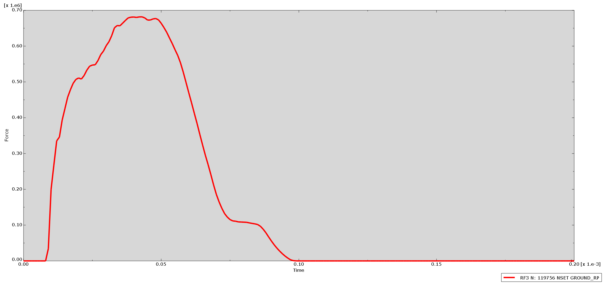
Then I ran the simulation:
Cross-section view - colored by instance
Cross-section view - colored by LE Max. Principal
RF3 on ground plane
Files
I’ve packaged up the important files generated by Codex that are necessary to replicate the meshes (and simulation inputs) shown above.
simulation_prep_share.zip (1.3 MB)
Oh, and I also asked Codex to compile some documents with the intention that I could share information with others (such as colleagues or customers). I mentioned during the webinar that I’ve often created slide decks showing the various defeaturing & model prep stages, for internal review or for checking with customers. I had Codex put this into a PowerPoint file (I uploaded the PDF of that below) and I will say I’m impressed with what it did there. I’m less impressed with the customer-facing engineering report, but admittedly I didn’t give much input to Codex.
This looks great! Finally, I’m making a forum post and want to share repeatible workflows for all four simulation pipelines (Sierra THex, Sierra Swept/Tied, Abaqus THex, Abaqus Swept/Tied) so that people can download the files and run them to produce simulation inputs. I don’t care about the post-processing etc., just simulation prep. Can you collect the necessary files into a directory that I can ZIP up? I don’t want every transient file, just the necessary ones.
customer_report_draft.pdf (2.5 MB)
model_preparation_review.pdf (6.2 MB)