Dear Community:
I am currently working on a dynamic rupture simulation using SPECFEM3D. My model involves two dipping faults with opposing dip directions (one dipping East and the other dipping West). Both faults rupture to the free surface and partially intersect in the middle section of the model.
I have encountered a challenge regarding the mesh quality. Specifically, in the intersection zone, the Equiangle Skewness of several elements exceeds 0.75. I am concerned that this high skewness may affect the stability and accuracy of my wave propagation and rupture results.
I have attached my journal file (.jou) below for reference:
mk_model.jou (29.0 KB)
Could anyone advise on how I might adjust my modeling process to reduce the mesh skewness and improve the overall mesh quality in these areas?
Any suggestions, tips, or guidance would be greatly appreciated. Thank you very much for your time and help!
Best regards,
YuanYi
Hello @will8304,
which version of Cubit are you running? Your journal produces some errors with Cubit 2025.12.
So i am not quite sure what the final geometry is.
Hello @Norbert_Hofbauer ,
Thank you for looking into my script.
I am using Cubit 2023.11.
Thanks again for your help and time!
Does your solver handle wedges?
As far as I know, it is strictly limited to hexahedral elements and does not support wedges or other types.
Sorry to bother you again, but I encountered another issue while reviewing the model.
The defined range for my model should be X: 230,000 to 330,000, Y: 2,490,000 to 2,640,000, and Z: -35,000 to 0. Although I don’t see any vertices or nodes outside this range, the “Bounding Box” of some volumes clearly exceeds these limits.
How can I adjust the volumes so that the Bounding Box aligns perfectly with my defined model range?
Thank you for your help!
Due to the geometry you can’t really improve the skew. I didn’t find a way yet.
About the bounding box. Can you draw the tight bounding box and compare its values. Doesn’t seem wrong to me.
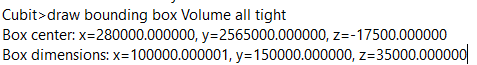
Yes, using the command you suggested, the results are the same as yours. However, when I run list volume all geometry, I noticed that the numerical bounding box for certain volumes is offset.
I suspect this was caused by the webcut operation on surfaces created via spline sweep. I managed to resolve this by copying the boundary curves of the cut volumes and using them to create volume again.
Thank you very much for taking the time to test my model!
