Sometimes in traditional FEA the analyst will apply a tie between the non-conforming surfaces, as long as it’s in a region sufficiently far away from the region of interest.
Series of questions I’ve been asked:
Do volumetric U-Splines allow for “T-Junctions”?
How would these non-conforming interfaces perform compared to tied interfaces?
How would these non-conforming interfaces perform compared to conforming interfaces?
Would the final image be a “good” non-conforming mesh?
Greg, yes we can do T-junctions on volumetric U-splines. We’re still working on making sure the algorithm that builds the basis on those cases is robust, though. We did some proof-of-concept tests to show, particularly, that we could build the basis on a T-junction between a hex and two tets, where the “T” goes diagonally across one of the faces of the hex. I also got an example working a couple weeks ago that has nested-T-junctions on a volumetric topology.
Although, for the example you showed I don’t think you’d need to use T-junctions – we could build a volumetric mesh on that example without T-junctions. It would require eight hexahedral cells, as far as I can see.
I’m not sure how to answer your other questions. What do you mean by “perform”? I don’t know what “tied interfaces” are. What do you mean by a “good” non-conforming mesh?
Generally speaking, a conforming mesh will tend to give more accurate results, especially at the interface between materials. Plus, it generally makes more intuitive sense to analysts.
However, for many problems, tying non-matching meshes together can often still give good results. I think either @mike, @florian or @mjborden could offer much better insight than I could into our capabilities for tying non-conforming mesh together.
That being said, the fact that we allow for T-junctions dramatically simplifies the problem of creating a good conforming mesh. As Steven pointed out, we are still actively researching T-junctions for volumetric U-splines. However, once U-splines become more fully developed and widely accepted, I think they will radically disrupt the meshing game, where hanging node (aka T-junctions) have traditionally been avoided at all costs.
Hope this helps, let us know if you have any more questions.
The example shown is mostly just for demonstration purposes.
In Abaqus, tied interfaces make the translational and rotational motion as well as all other active degrees of freedom equal for a pair of surfaces. By default nodes are tied only where the surfaces are close to one another.
In practice they’re often used as a last resort in the meshing process, to connect a coarse region with a refined region, or to connect two regions that use two incompatible element types (Hex-Tet). For example, a coarse quadratic tetrahedral mesh in the far-field might be tied to the boundary of a refined hex mesh - this boundary being sufficiently far from the region of interest to remove boundary effects that arise from this tied interface.
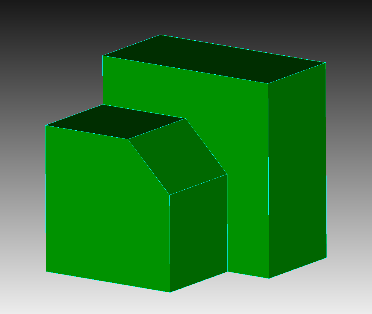
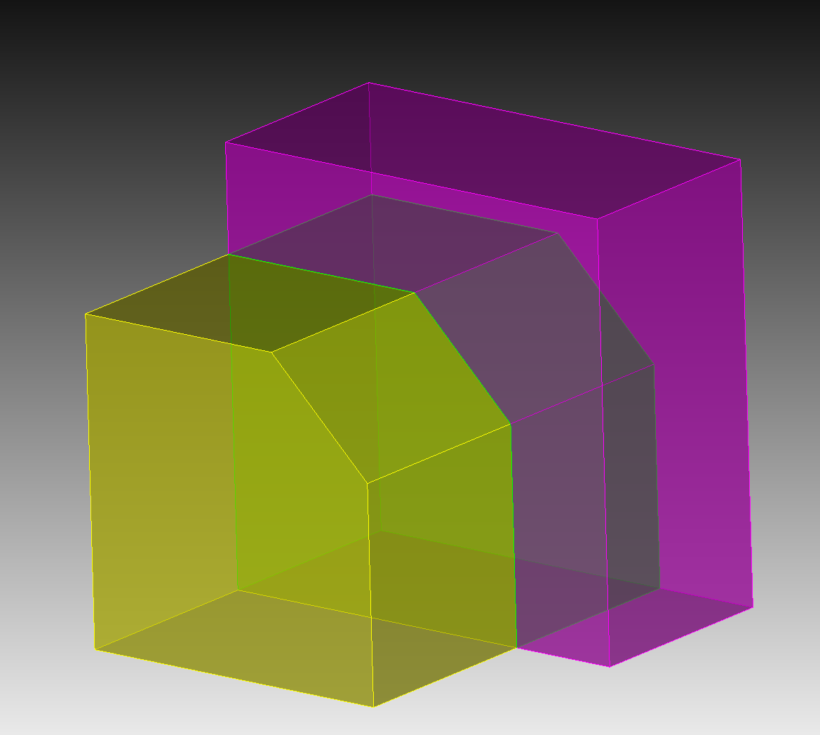
Here are two instances where I might hex mesh an easy region while tetmeshing a more difficult one (parts from the publicly-available NIST repository)
However, for many problems, tying non-matching meshes together can often still give good results.
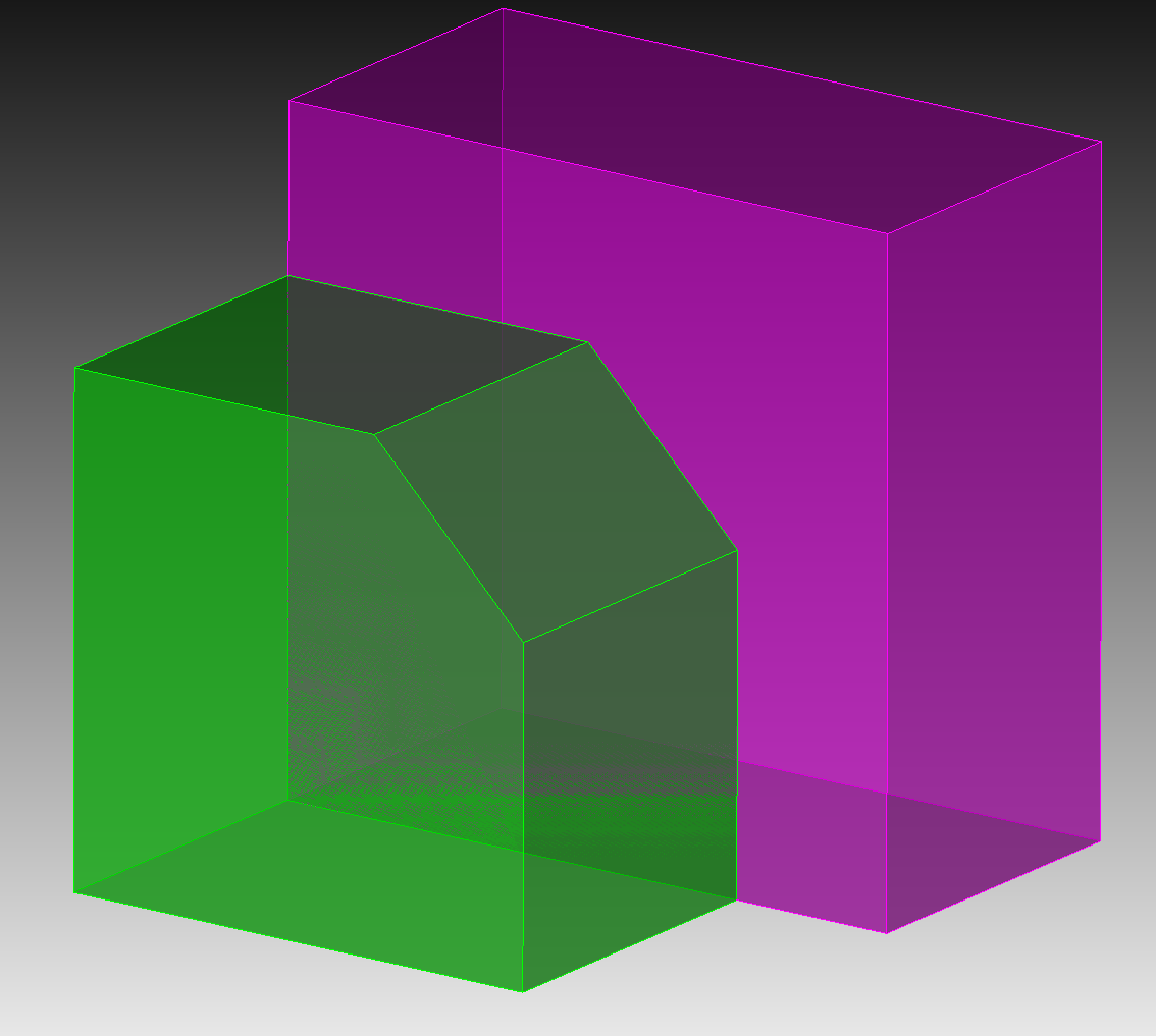
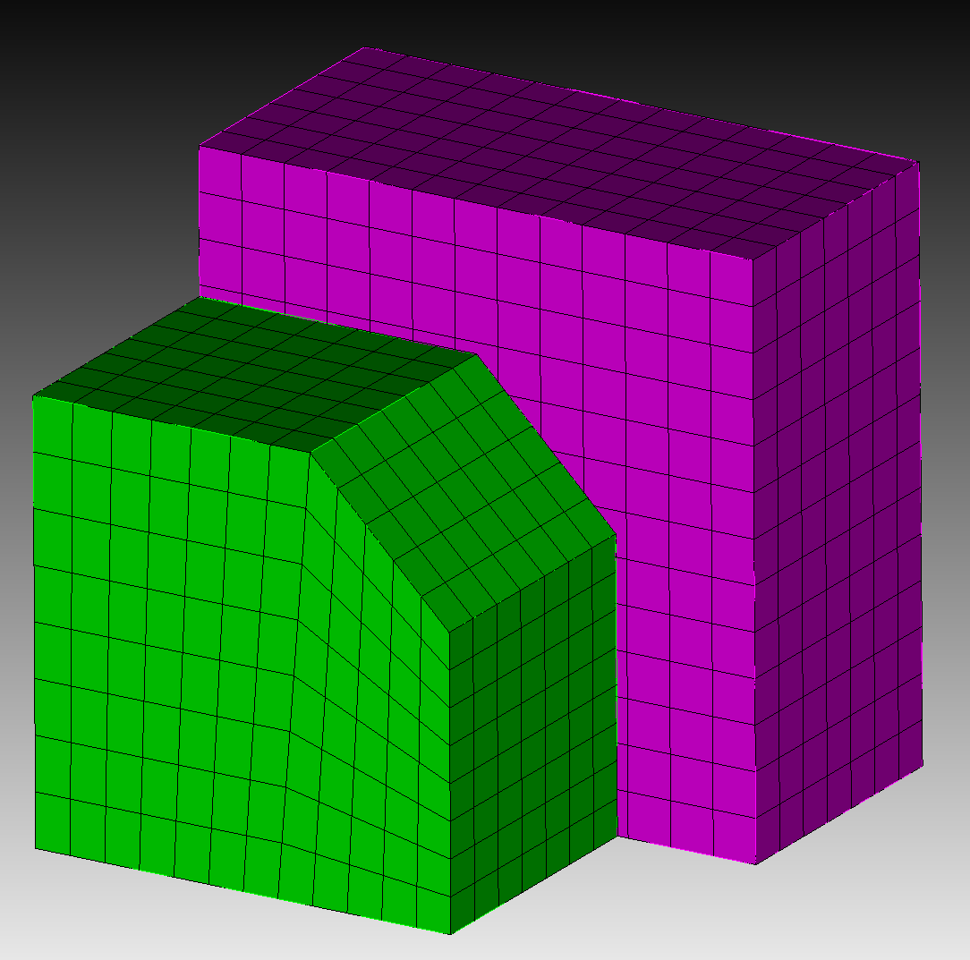
Just to be clear, when you say “tying non-matching meshes” are you meaning tying in the traditional sense, or via T-junctions & U-Splines? It does get a bit confusing when thinking about elements that allow for T-junctions. The mesh below, with traditional structural mechanics elements would be a non-conformal mesh, but what should we call a mesh like this if it’s built with T-junctions via U-Splines? Is it a conformal mesh?
Long term, I would rather use T-junctions on these interfaces if they are superior to ties. This would seem like a big win.
Greg, this is a really good point. If we built the above mesh using U-splines, then I would indeed call the resulting mesh conformal.
In the classic FEA approach, hanging nodes at an interface lead to discontinuities in the basis used to represent the solution (see below). In this case, to tie the non-conforming cells together and enforce continuity, the hanging node could be constrained to lie exactly between the two control points circled in blue.
The key advantage to using U-splines is that these continuity constraints are built directly into the U-spline basis functions. Notice that for a linear, C0 U-spline, there is no control point at the T-junction, since this degree of freedom is constrained away by the C0-continuity constraint.
Luke, thanks! This is a good visualization and description of what’s going on, moving forward I will try to remember to call meshes of the bottom image “T-junctions” under the understanding that they are indeed conformal.
It might be good to supplement future presentations with this sort of description / visualization. Specifically, I’m thinking of the T-junction examples that were used in the seminar (see below). I think your description would be a good addition to help contrast traditional FEA to smooth-spline FEA.
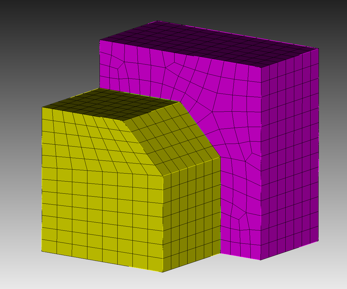
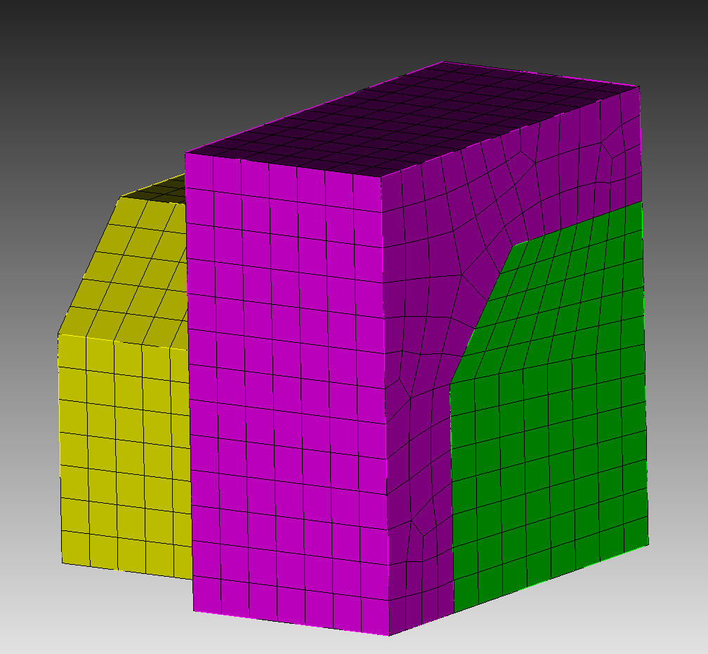
Because these volumes were meshed independently (and ignorantly) of the other volume, there are nodes & edges that would seem to be “poorly” located. I’ll pick a couple examples to delve into more:
Here is an extraordinary point that lies very close to an element interface on the other surface. Could this point be supported as-shown in a U-Spline? It would seem to me that in order to support this point it would effectively require some small feature that in an explicit dynamics problem would require an extremely small time step to allow. And that in an implicit case this might lead to poor conditioning. Thoughts?
Here is an element that on the bottom left has two nodes within the face of an element in the other surface. Would such a layout be supported by the U-Splines algorithm? The other two nodes of the element lie in two diagonally adjacent elements, and the edge connecting them passes near a node in the other surface. Would this layout be supported? Would either of these layouts have similar concerns to those I raised in the previous paragraph?
Essentially, it’s still a bit unclear to me whether U-Splines support fully-unstructured T-junctions (my examples don’t look very much like "T"s) or whether they still require some “semi-(un)structured” layout, similar to the examples that are shown in Coreform’s presentations.
At this point we are assuming that the T-junctions do have some “semi-(un)structured” layout. Generally for volumetric U-splines, the T-junction will be some subdivision of a quad face into a collection of smaller quads, or a split of a quad face into two triangles.
So, you’re correct to question if we could support fully unstructured non-conforming interfaces, as shown in your example; at this point it’s not something that we support. However, the ability to add T-junctions does significantly simplify the the problem of creating some “semi-(un)structured” conforming layout for which we can build a valid U-spline basis.
A question was asked during the seminar about U-Splines for fully-unstructured tet & tri meshes. @derek’s response was something like, “We do not support C>0 on these meshes at this time, but we believe the U-Spline theory is general enough to work on these meshes; we see no reason why it wouldn’t.” So, practical considerations aside, would the U-Spline theory “work” on a fully-unstructured non-conforming interface, as shown in the examples above, with a similar line of reasoning to Derek’s?
@gvernon, it is possible that it could work. The way we formulate things now, the biggest requirement is that the basis on one side be represented in terms of the basis on the other side. This is possible for simple geometries but for completely arbitrary interfaces you would probably be better served by doing something other than trying to build a U-spline over the whole thing. We have some new methods for building these connections but haven’t done enough research to say how they will affect the stresses, etc.
Sitting at the short-course, @mike is talking about Bezier dual mortaring. Seems like this problem might fall under that class of mesh solution (weak coupling). This is a reminder to myself to look more into this…