Hi
A (very) basic question: after skinning a mesh, is it possible to hide 3D elements ? I dug into the documentation, but nothing is obvious for me.
Tanks
Paul

Hi
A (very) basic question: after skinning a mesh, is it possible to hide 3D elements ? I dug into the documentation, but nothing is obvious for me.
Tanks
Paul
Hi Paul,
Your question isn’t completely clear to me. If you are talking about visualization, Cubit always just draws the 2D elements in the skin by default. It will only draw the 3D elements if you specifically ask for them, for example draw hex all.
If you are talking about exporting only the 2D elements, you can place the 2D elements in a block and export the single block. This would “hide” the elements from the analysis code. For example, the commands below would add all the 2D quadrilateral faces into a block and export those.
block 1 face all
export mesh '2d_elements.e' block 1
Hi,
I’m speaking about visualization.
To be more clear, using skins is a good way to check if the mesh is full conform; it avoids possible mistakes (and it’s more relevant rather than simply looking for duplicate nodes) - i’ve ever experienced such troubles with several mesh tools.
Paul
Like I said the default is that Cubit draws only the skin. You can turn on the clipping plane to see internal surfaces.
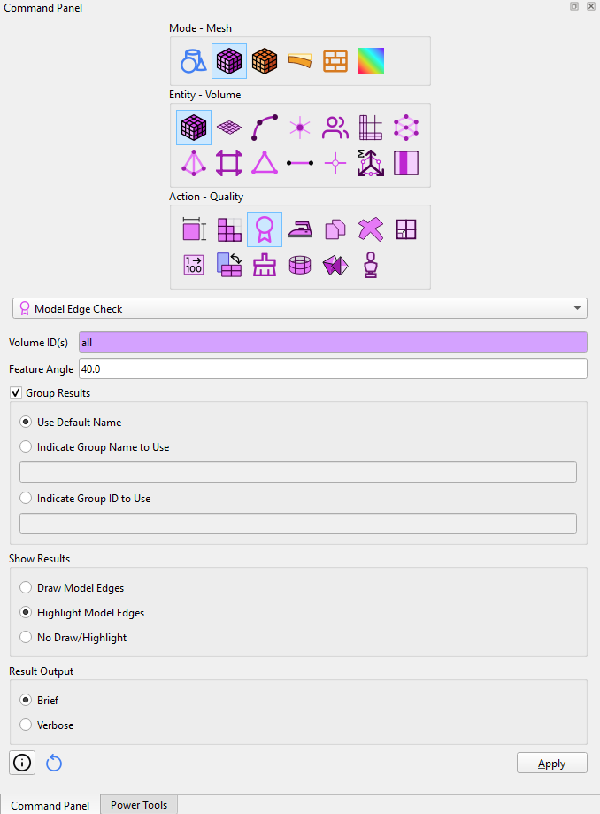
The main purpose of doing the imprint and merge steps in Cubit is to give complete control of the conformal mesh. If curves and surfaces are merged correctly, you are guaranteed a conformal mesh. You can use commands like draw curve with is_merged or draw surface with is_merged to display the merged pieces of geometry. There is also an icon that colors curves by the number of merged surfaces at the curve.

Blue curves are linked 2 surfaces, gold curves are edges of non-manifold surfaces, and white curves are linked to more than 2 surfaces.
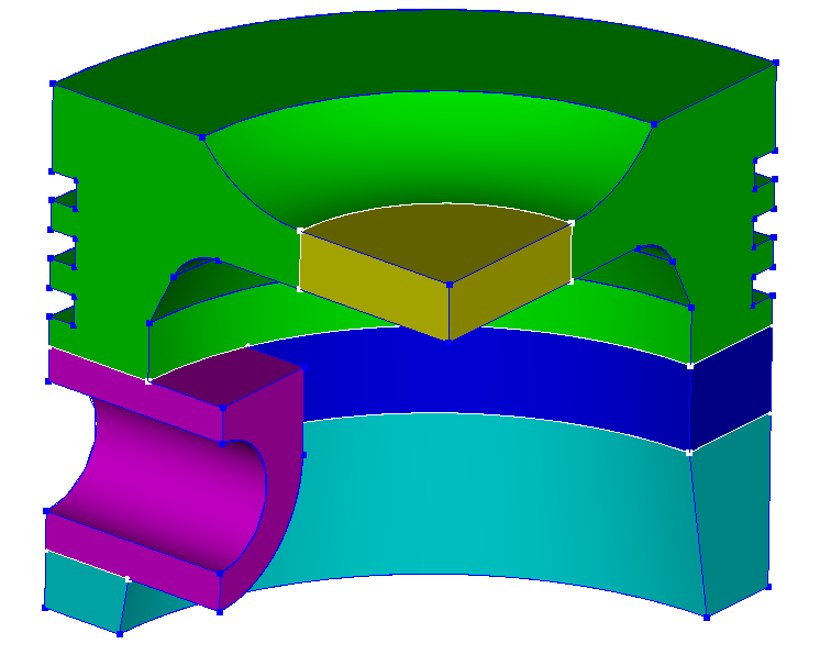
Here’s a script that runs on the attached STEP file. I believe what you’re looking for is to first add the skinning to a block (or sideset or group) and then draw block <n>. To “cleanup” when done (if desired), simply delete the block.
piston.stp (56.4 KB)
# IMPORT GEOMETRY
reset
import step "piston.stp" heal

# REDUCE TO QUARTER-SYMMETRY
section volume 1  with xplane offset 0 normal
section volume 1  with zplane offset 0 normal

# SET ASSIGNMENT
block 1 vol all

# WEBCUT FOR MESHABILITY
webcut volume 1  sweep surface 71  perpendicular inward through_all
webcut volume 1  sweep surface 84  perpendicular inward through_all
webcut volume 1  with plane normal to curve 58  close_to vertex 49
webcut volume 1 with plane from surface 85

# ENFORCE CONTINUOUS MESH
imprint all
merge all

# GENERATE MESH
mesh vol all

# USE SKINNING TO VERIFY MESH CONTINUITY
skin Volume all make block 2
draw block 2

# REMOVE SKINNING
delete block 2
Note that there are other ways that can be used to visually verify mesh continuity:
Show Curve Valence button is_merged keyword with various commands to render merged (or unmerged) entities:draw surface with is_merged
draw surface all except with is_merged
color surface with is_merged white
Model Edge Check quality check:OK: different tool / different philosophy / different strategies: checks must performed on the geometry! => Thanks for sharing these (so) precious snippets
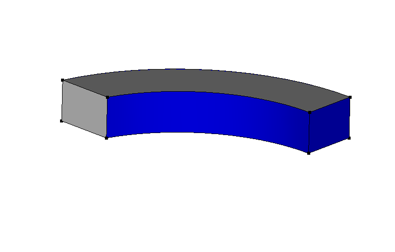
I manually meshed a basic part I’ve found, mainly to do tests … but the road is still long.
Thanks for the support
Simetricen_nosilec.cub5 (6.4 MB)
To be clear, I do think that your approach of skinning the hex mesh and then drawing the skinned mesh (with transparency) is a very useful approach for verifying continuity of the mesh. The other methods I mentioned are simply other ways of verifying or trouble-shooting. Each approach has their own pros/cons, so it’s useful to know about each of them.
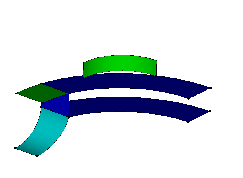
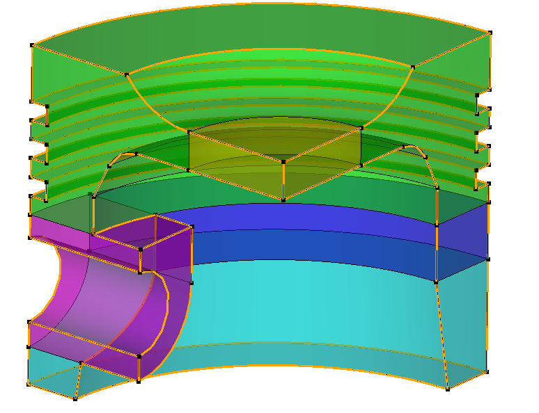
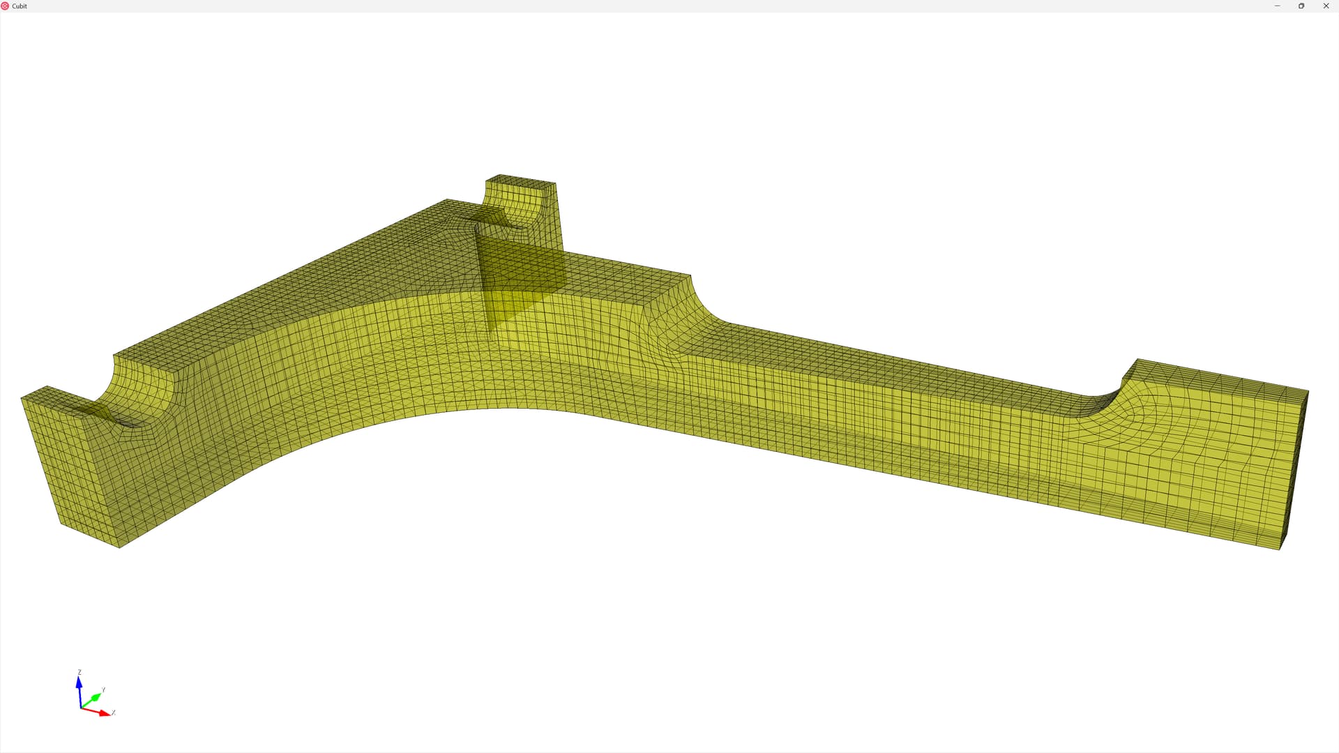
Just to follow up on my previous comment, I like your approach using skinning because with transparency you can then verify that there aren’t any interior surfaces (or at least none where they shouldn’t be) which would represent a non-conforming mesh at those surfaces. So here’s the results of your skinning approach on your CUB5 file.
reset
open "Simetricen_nosilec.cub5"
skin vol all make block 2

graphics mode transparent
draw block 2
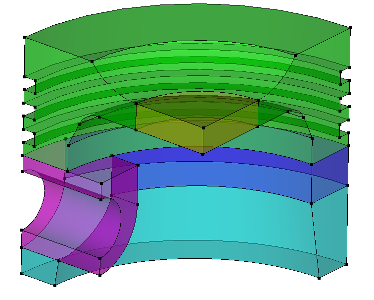
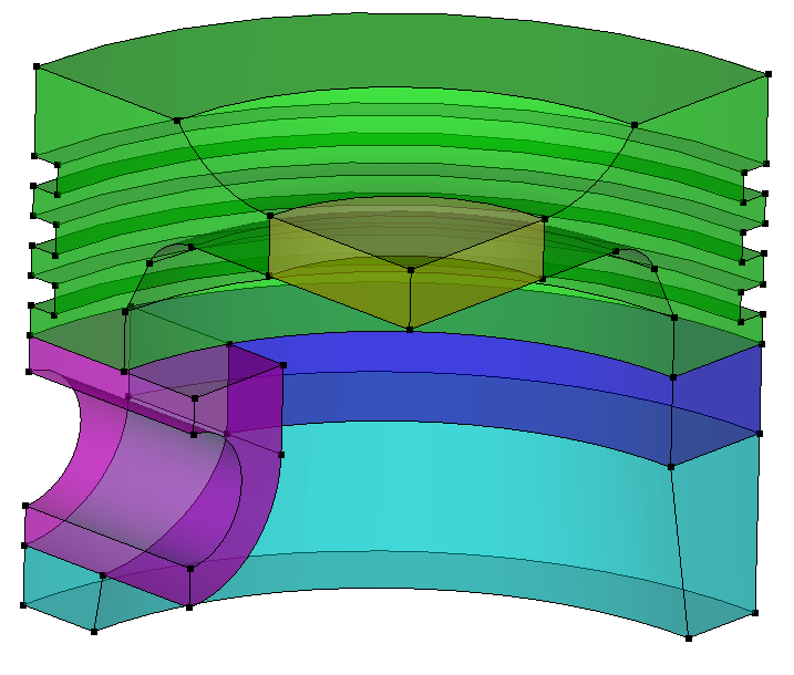
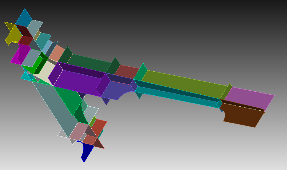
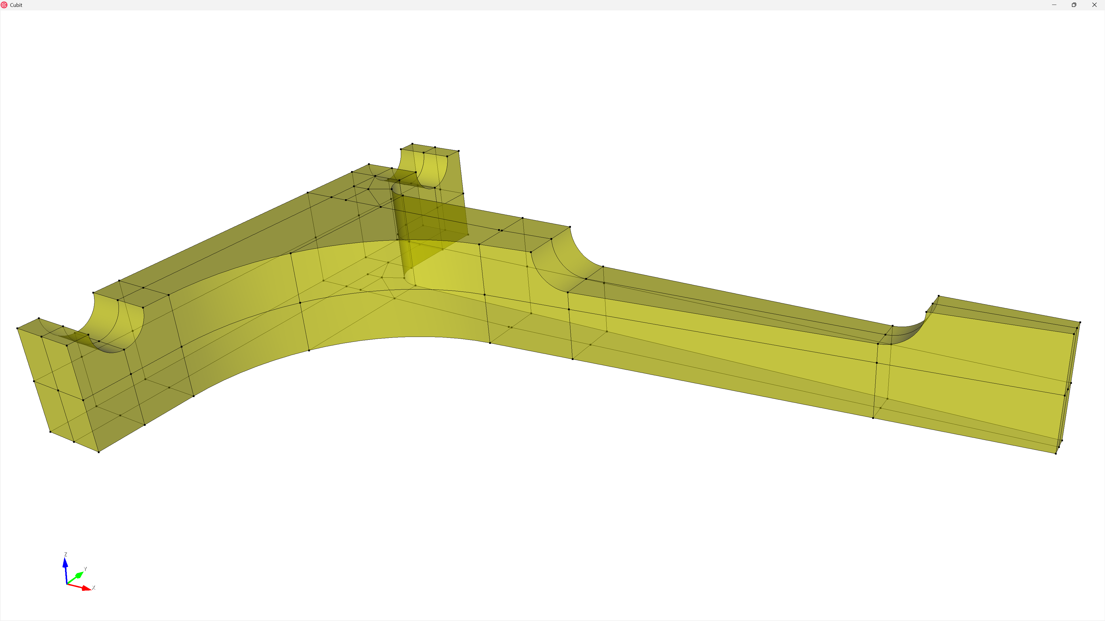
and:
reset
open "Simetricen_nosilec.cub5"
skin vol all make block 2

mesh visibility off
graphics mode transparent
draw surface in face in block 2
color surface in face in block 2 yellow # Optional