The Coreform Flex GUI
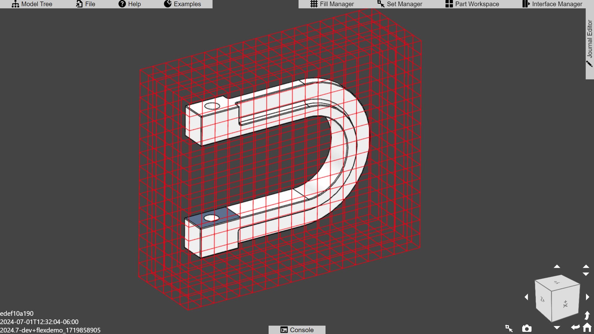
Here is the Coreform Flex graphical user interface (GUI) as viewed within a web-browser in full-screen mode (shortcut is usually F11).
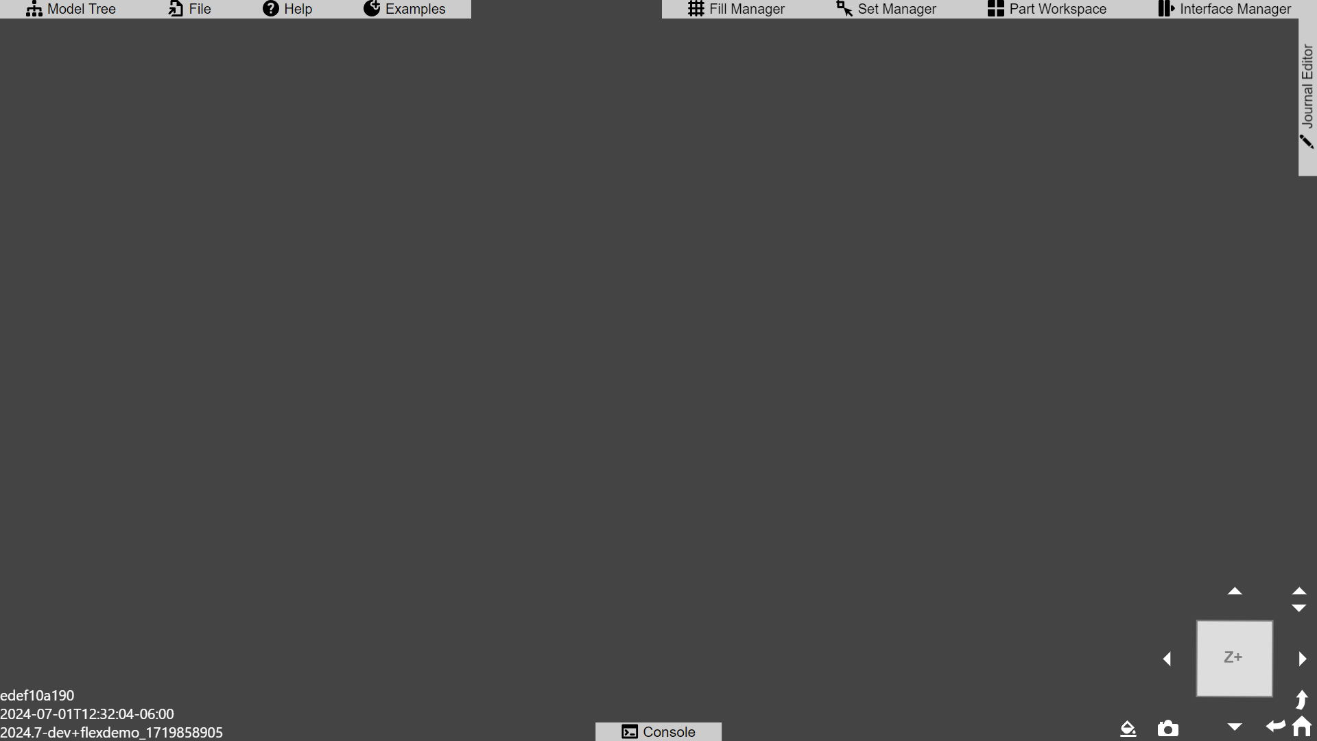
And here is the same image, overlayed with numbers which we will describe below. Note that these descriptions will be short, with more in-depth documentation in separate posts.

1. Model Tree
This button toggles an overlay containing the model tree. Currently, the Coreform Flex model tree contains three sub-trees:
- Geometry
- IGA
- Job Manager
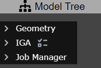
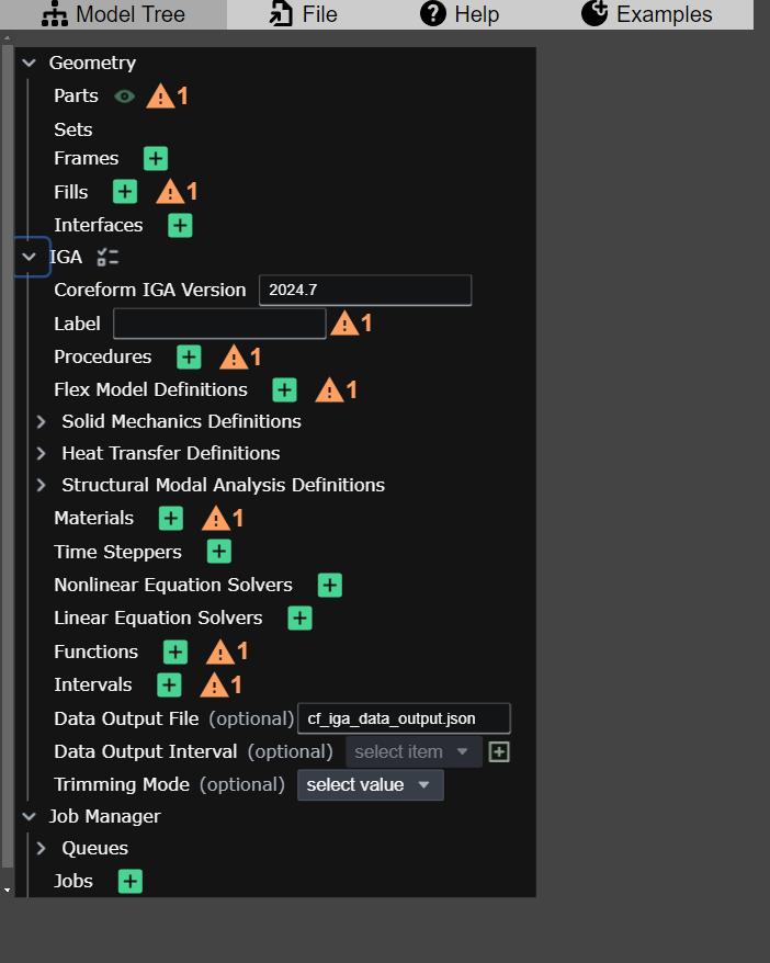
To expand any of these trees, or the objects within, click on the > button – once expanded the button will be rotated into a v shape, clicking it again will collapse the item.
Both the Coreform Trim executable (which performs the volumetric trimming operations that produce the trimmed mesh used by Coreform IGA) and the Coreform IGA solver use input files in the JSON5 input format. These model trees reflect these input files in a 1:1 manner. Users will rarely directly modify the input file corresponding to the Geometry subtree, however users may wish to directly edit the IGA input files in a text editor – the model tree can be used to discover syntax structure and is therefore, in effect, documented in the IGA Reference Manual.
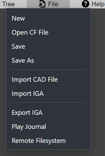
2. File
Provides several shortcuts for resetting, importing, and exporting files from Coreform Flex
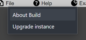
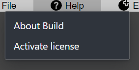
3. Help
In the browser-based application, hosted by Coreform, this provides the ability for users to upgrade their instance while, in locally-installed applications will instead provide the ability to activate licenses.
Browser-based
Local installation
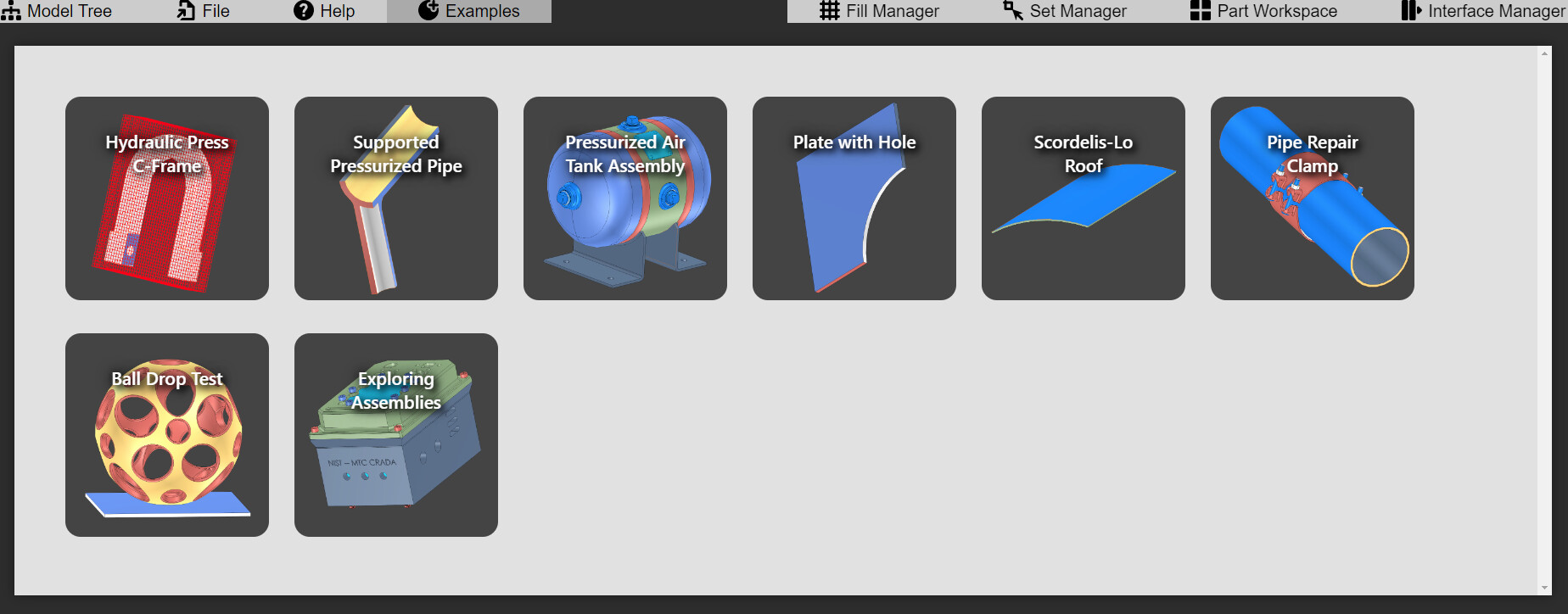
4. Examples
This button brings up a panel allowing users to open examples provided by Coreform:
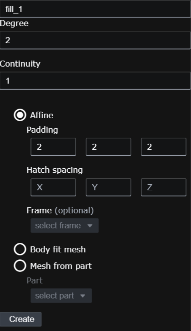
5. Fill Manager
A “Fill” is a term introduced by the Coreform Theory Manual that replaces the term “Mesh” in traditional FEA and CFD. The Fill Manager, then, allows users to create and assign fills to models.
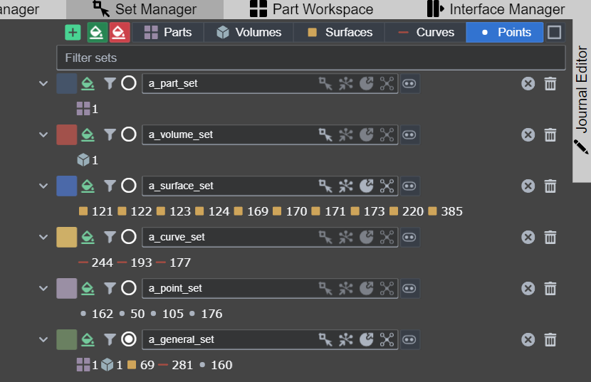
6. Set Manager
The Set Manager shows and provides users with tools needed to assign various entities to sets that can be referenced by Coreform IGA input parameters.
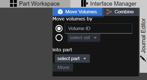
7. Part Workspace
The Part Workspace provides simplified workflows for modifying parts within the Geometry tree. Note that the term “Workspace” is used here because it does not provide the user with comprehensive part management capabilities.
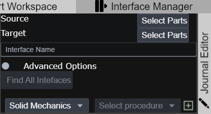
8. Interface Manager
The Interface Manager provides simplified workflows for identifying and creating interfaces between parts. Currently the only interfaces supported are material interfaces, that is bonded-material interfaces between parts – the equivalent of contiguous meshes between parts in traditional FEA.
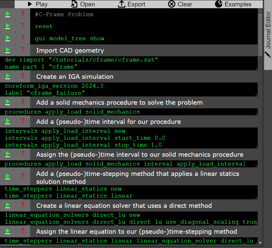
9. Journal Editor
The Journal Editor provides a simple interface for creating, editing, and playing journal files that automate model setup.
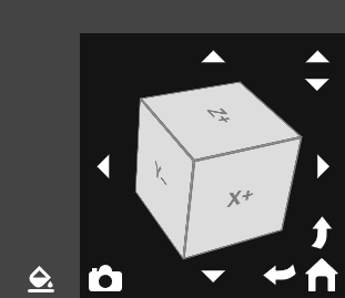
10. View navigation and rendering options
These provide tools for changing the view in the render window, such as snapping to a view-plane, returning to the home view, or rotating the view by 90-degrees. It also provides a screenshot button and a paint-bucket button that can change the “color-by” rule.
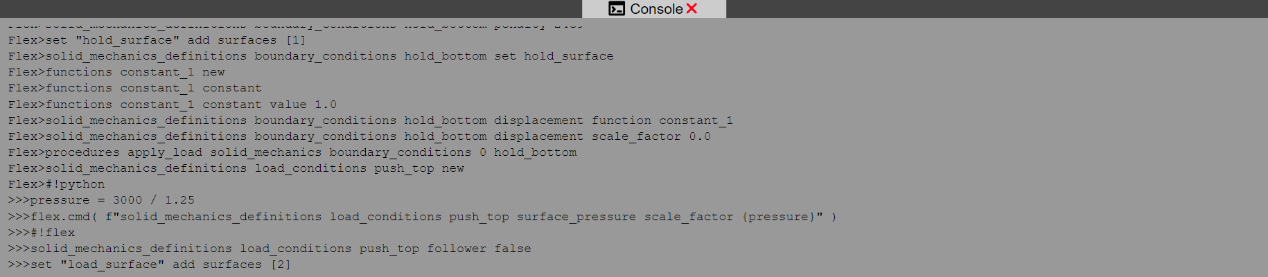
11. Console
Coreform Flex has its own native command language. Currently this language closely reflects the structure of the model tree, however more-sophisticated capabilities are actively developed. Coreform Flex also supports a Python API through the flex Python module which is available through the console by switching to the Python entry-mode.
To switch to the Python-entry mode, run the shebang #!python in the console when in the Flex entry-mode, and use #!flex to switch from Python back to Flex.
12. Remote Build Information
This is only shown if using a Coreform-hosted instance of Coreform Flex through your web-browser and provides helpful information about which version of Coreform Flex you’re using.
13. Render View
This is where your model’s geometry and other objects are rendered. You can interact with the model to select entities, perform queries, and more.