
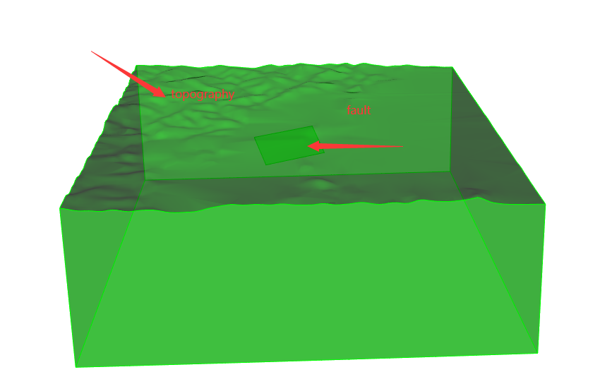
How to mesh the topography model embedded in faults (the top surface is the terrain, and the inclined rectangle is the fault)?Please help solve this problem.
Hi Jinchiwang,
Welcome to the forum. Is your model CAD geometry or STL (facet-based) geometry? Do you require a hexahedral mesh, or is a tetrahedral mesh sufficient? II
There are different methods to solve this problem depending on your needs.
Given a volume and surface embedded in it. Here is one solution. This solution would also work if the model is an STL model.
undo on
reset
brick x 10 y 3 z 10
create surface rectangle width 2 height 1.2
body 2 rotate 15 about z
body 2 rotate -25 about x
body 2 move z -2
surf 7 scheme trimesh
surface 7 size 0.1
mesh surface 7
vol 1 scheme tetmesh
volume 1 size 1
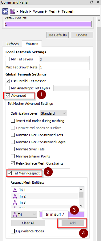
vol 1 tetmesh respect tri in surface 7 # the command panel expands this to a list of all triangles.
set tetmesher optimize level 4
mesh vol 1
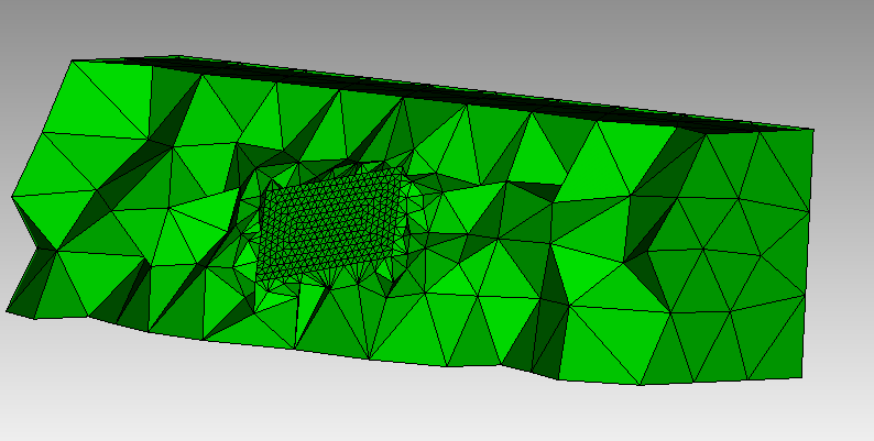
# some visualization commands to help see the mesh
draw tet all
# turn on graphics clipping and position it so the plane is normal to the surface and offset just a little to see the triangle mesh.
graphics clip on plane surface 7 reverse location surface 7
graphics clip on location position {Vx(9)} {Vy(9)} {Vz(9)+.05} # Use the X, Y, and Z locations of vertex 9
graphics clip manipulation off # turn off the interactive clipping plane
Here is the Mesh/Volume/Mesh/Tetmesh panel showing the options that are selected in the GUI.
Thanks,
Karl
Hi Karl,
My model is an STL geometry, and I need to generate a hexahedral mesh. Is this similar to the way tetrahedral meshes are generated?
Thanks
Jinchi Wang
Dear Karl,
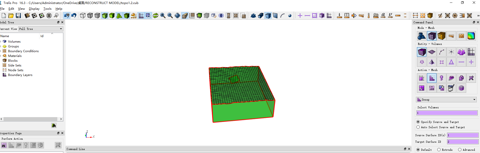
My model is an STL geometry, and I need to generate a hexahedral mesh.I tried to mesh the volume using the following command, but the following error occurred. How can I solve this problem?
reset
open “C:/Users/Administrator/OneDrive/桌面/experiment/topo.cub”
sweep surface 1 vector 0 0 -1 distance 50000
webcut body 1 with plane zplane offset -40000
delete volume 2
compress all
create vertex 287332 3360103 -17800
create vertex 306889 3370310 -17800
create vertex 301967 3379742 -7801.90
create vertex 282410 3369535 -7801.90
create curve vertex 9 10
create curve vertex 10 11
create curve vertex 11 12
create curve vertex 12 9
create surface curve 13 14 15 16
compress all
subtract body 2 from body 1
compress all
surface 1 scheme pave
surface 1 size 4000
mesh surface 1
volume 1 size 4000
volume 1 redistribute nodes off
volume 1 scheme Sweep source surface 1 target surface 2 sweep transform least squares
volume 1 autosmooth target on fixed imprints off smart smooth off
mesh volume 1

Hi Jinchiwang,
The error messages seem to indicate that the curves along the edges are not well defined. Can you upload your STL file?
I’ve been doing some research on your original question as well. There may be a method to use the sculpt algorithm to cut the hex mesh and create fairly complex fault regions. I am still investigating that.
Thanks,
Karl
Hello Karl,
I’m sorry for not replying so later. Thank you very much for your help. The following compressed file is related to STL.
Thanks,
JC Wang
cubitfile.zip (2.2 MB)
Hi JC,
You have the model as ACIS geometry in Cubit. I would create the initial hex mesh from the CAD and not move it to STL until you need to. I don’t know the depth of your geometry and mesh size is fairly coarse, but does something like this work for you? l used the bounding box just to get an appropriately sized sized surface to loft to.
open "~/Downloads/cubitfile/topo.cub"
create brick bounding box Volume 1  tight
tweak surface 2  offset 2.5e4 # set your deptth appropriately
surface 2 copy
delete volume 2
create volume loft surface 1 8
delete body 1 3
compress
webcut volume 1  with general plane z offset -23000  # make the bottom plane parallel with Z
delete volume 2
vol 1 size 3000 # set your mesh size
mesh vol 1
Thanks,
Karl
Hello Karl,
I’m sorry for replying to you so late.Thank you very much for your guidance. I have another question to ask you. If my grid model has already been generated, how to export high-precision grid graphics and whether it needs to be processed in other software. Exporting images in these formats will result in distortion.
Best,
JC Wang
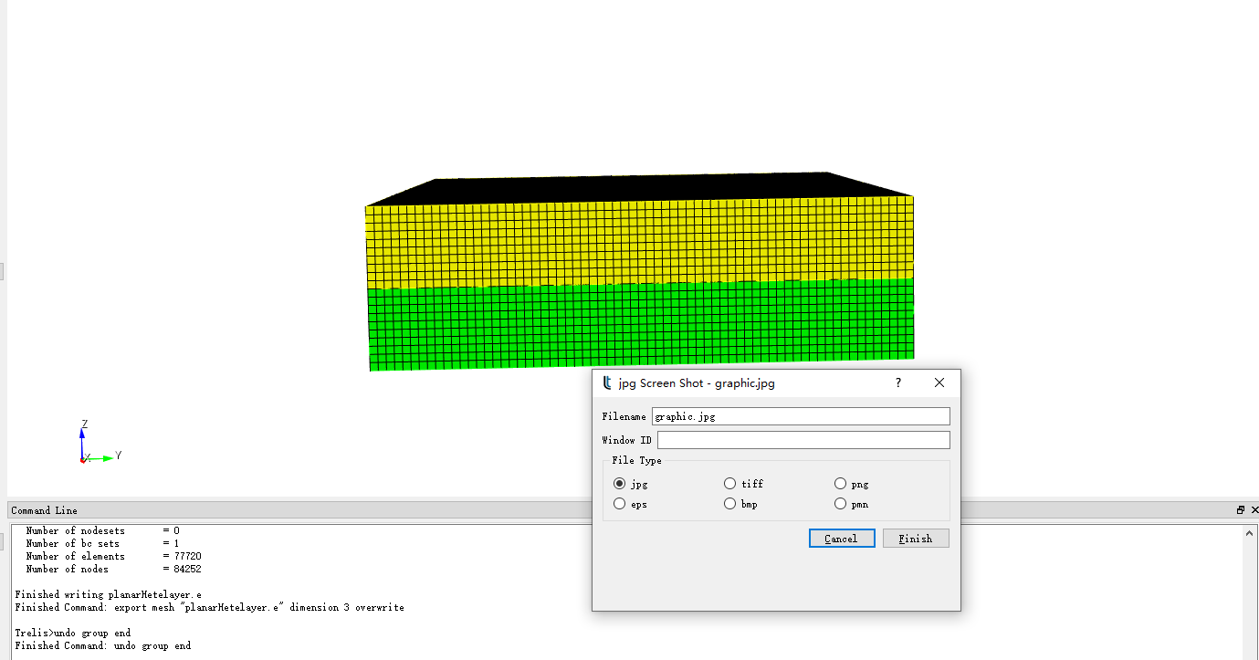
Unfortunately, Cubit does not have great anti-aliasing of grid lines. Any jagged lines you see on the screen will also appear in any screen shot.
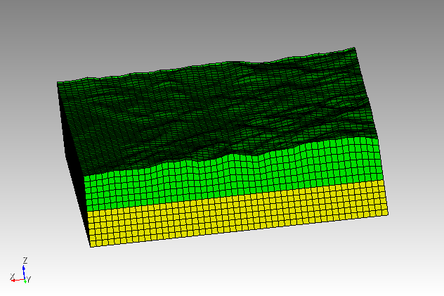
The “splotchy” curves at the interfaces can be fixed in one of two ways. If you just have straight lines, you can issue the command,
curve all color black
That will avoid the problems in the graphics z-buffer where the geometry curves gets drawn in yellow and the mesh edges are drawn in black.
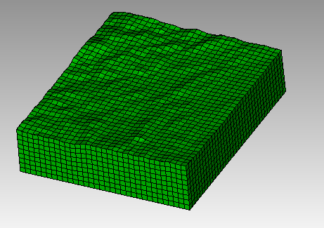
The other way to fix the problem is just to draw the mesh without the geometry.
draw hex all
That will only draw the hex elements with the black mesh edges and not attempt to render any geometry. That will clean up the interface curves as well.
Here is a version using the draw hex all command.
You still get jagged lines at the mesh edges but it looks better at interface curve.
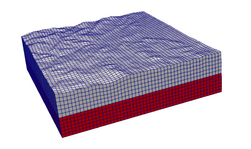
Alternatively, you can use a separate tool like Paraview to get better visualization.
From Cubit export the mesh to Exodus II format.
export mesh 'topo.e'
Start Paraview, import the Exodus file. Set the paraview render mode to “Surface With Edges” . Paraview has better anti-aliasing and removes the jagged lines.
Does this help with this problem?
Hi Karl,
This has greatly helped me. Following your guidance, I have solved this problem using Paraview. Thank you very much.
Best,
JC Wang