
Overview
In this tutorial, we present an approach to hex-meshing a small assembly of an automotive door lock, and along the way we’ll provide some tips for working with assemblies in Coreform Cubit.
Geometry
The geometry for this tutorial comes from this GrabCAD project by Bhaskar Mandloi.
For your convenience, here is a CUB5 file that will serve as our starting point:
Door_Lock_Assembly.cub5 (1.8 MB)
Meshing workflow
Opening the CUB5 file
We begin by opening the CUB5 file provided above.
#!cubit
reset
import cubit "Path/To/Door_Lock_Assembly.cub5" nofreesurfaces attributes_on separate_bodies
TIP: Switching between Cubit Command Language (CCL) and Python
Coreform Cubit’s command line and journal files now support switching between CCL and Python using “shebang” syntax. Note here that using #!cubit will switch to CCL while using #!python would switch to Python.
Assembly meshing
Coreform Cubit natively produces the Exodus mesh format, an open-source mesh format maintained by Sandia National Labs. Exodus defines sets using a few different terms:
-
Block: Defines regions upon which “body” simulation entities are to be applied, such as material models, element types, body forces, output regions, etc. -
Sideset: Defines ordered boundary sets on surfaces or curves. The ordering is necessary for simulation entities on boundaries that need to be integrated (e.g., pressure), compute normals (contact), etc. -
Nodeset: Defines an unordered set of nodes, typically for defining simulation entities that operate on degrees of freedom (e.g., Dirichlet boundary conditions, solution probes).
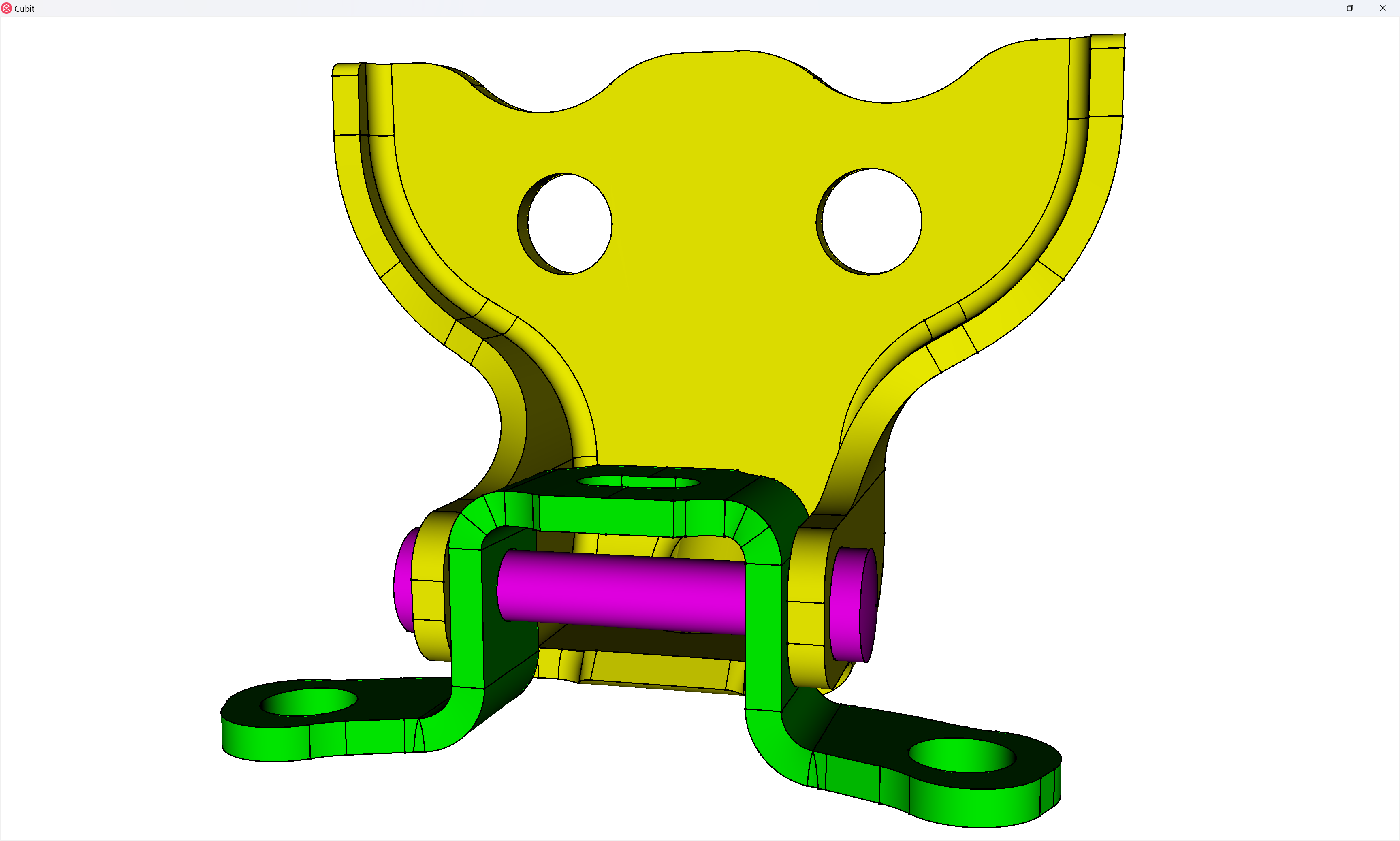
Since we’re working with an assembly, we’re going to want to use block assignments in our simulation to define parts/instances in our simulation, so before we begin meshing we’re going to assign blocks. The three blocks we’re going to create are: 1: door_link, 2: door_hinge, 3: door_pin. We can create these each in the GUI:
But this can get pretty repetitive and use a lot of button clicks for large assemblies, so I usually recommend using Coreform Cubit’s integrated Python API. Note that here I’m defining my desired block assignments via a Python dict, but in my former work-life within an engineering enterprise I’d often export Bill of Material information from our CAD software to a text file that I’d read into Python and process.
#!python
block_info = { "door_link":  { "block_id": 1, "volumes": (1,), "element_type": "HEX8" },
               "door_hinge": { "block_id": 2, "volumes": (2,), "element_type": "HEX8" },
               "door_pin":   { "block_id": 3, "volumes": (3,), "element_type": "HEX8" },
 }
part_names = list( block_info.keys() )
for i in range( 0, len( part_names ) ):
  block_name = part_names[i]
  block_id = block_info[block_name]["block_id"]
  block_volumes = block_info[block_name]["volumes"]
  block_element_type = block_info[block_name]["element_type"]
  cubit.cmd( f"block {block_id} volume {cubit.get_id_string( block_volumes )}" )
  cubit.cmd( f"block {block_id} name '{block_name}'" )
  cubit.cmd( f"block {block_id} element type {block_element_type}" )
Obviously, this requires a significant amount of code that you might not want to write when you first start meshing – this is more of a “finished state” – so I’ll usually start with a much simpler bit of code:
V = cubit.get_entities( "volume" )
for vid in V:
  cubit.cmd( f"block {vid} volume {vid}" )
And then after I’ve figured out my meshing strategy I’ll worry about the more sophisticated approach. The next thing I’ll do is process each block (part) one at a time.
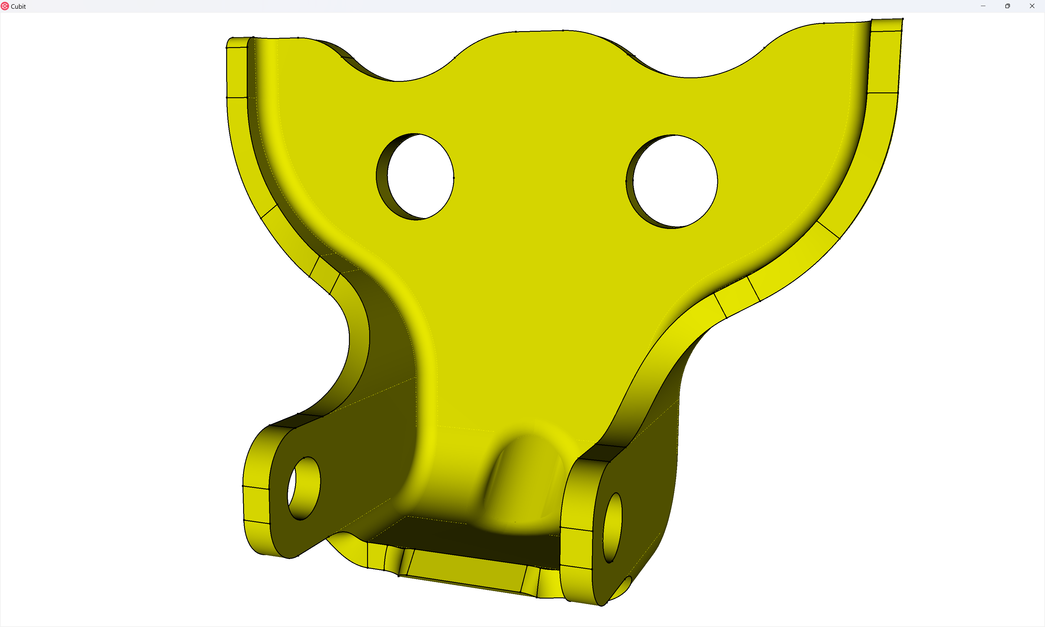
Meshing the door link
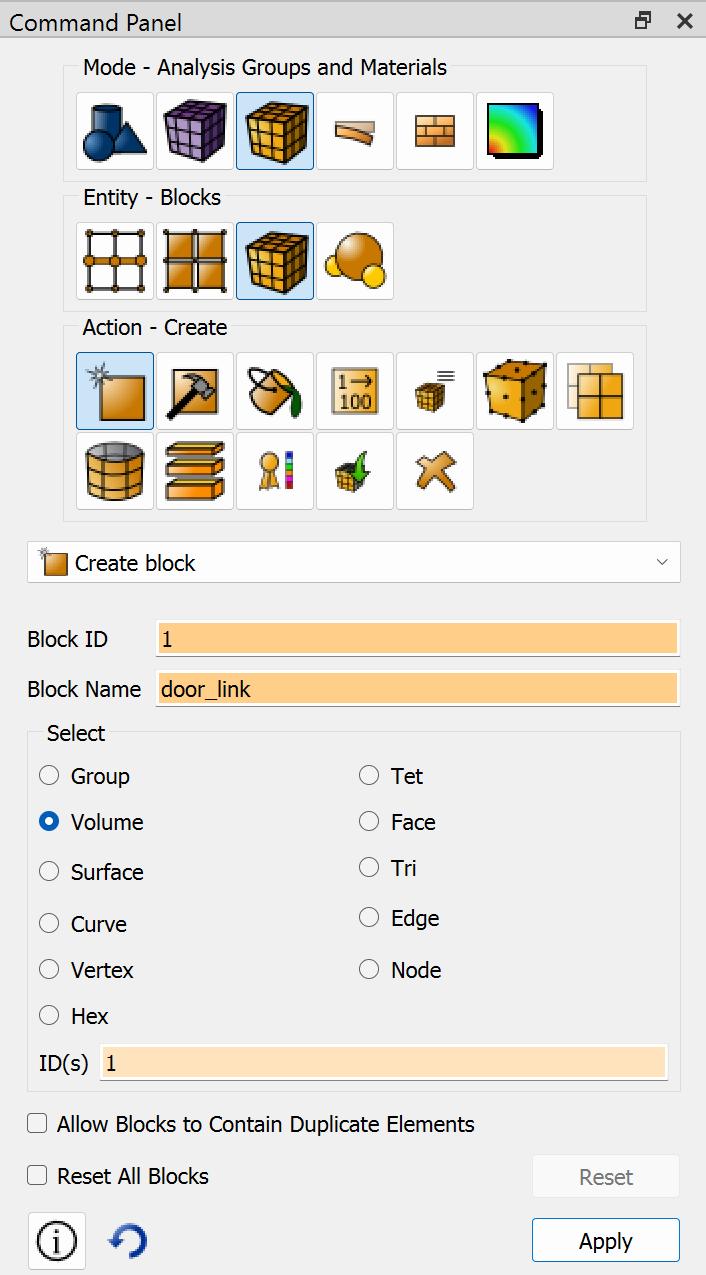
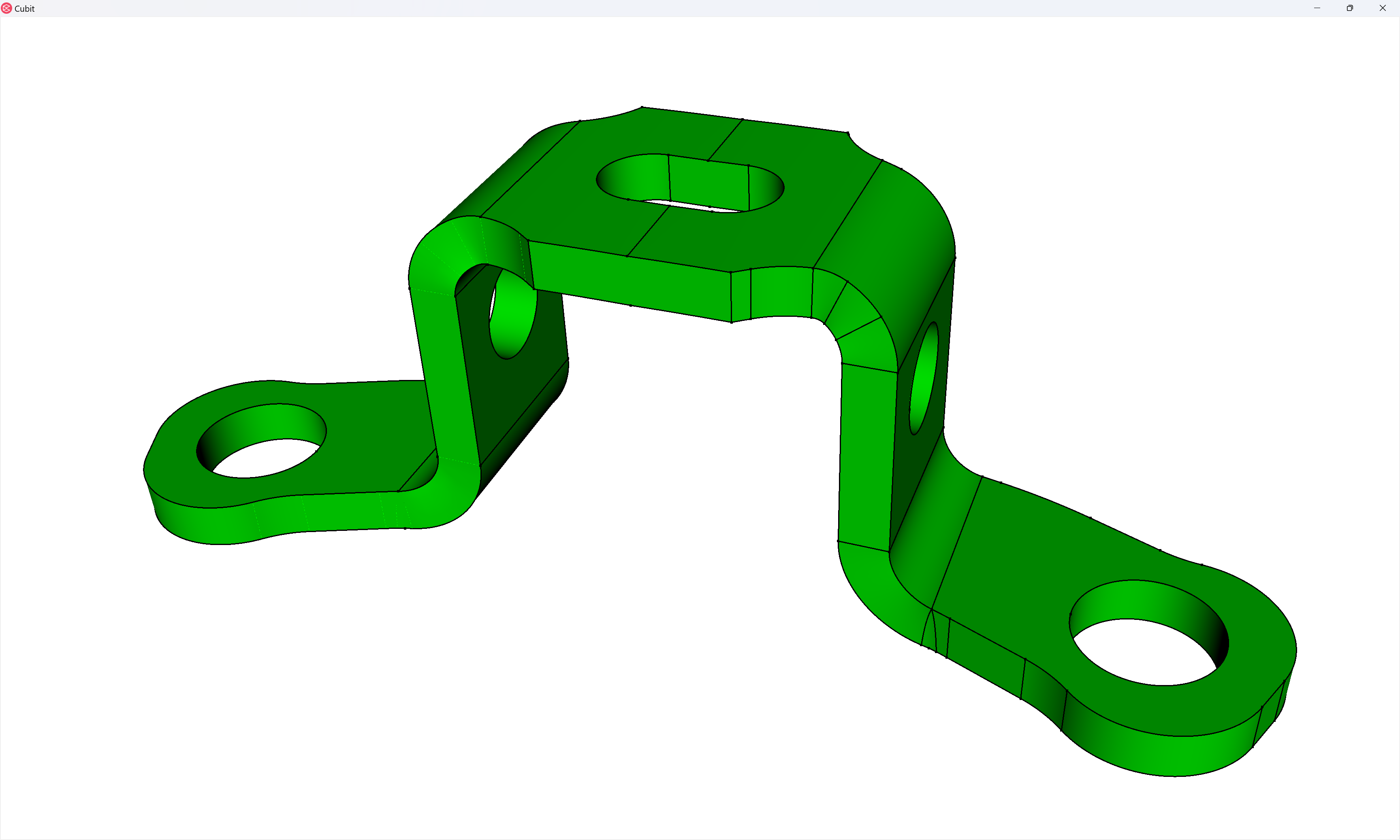
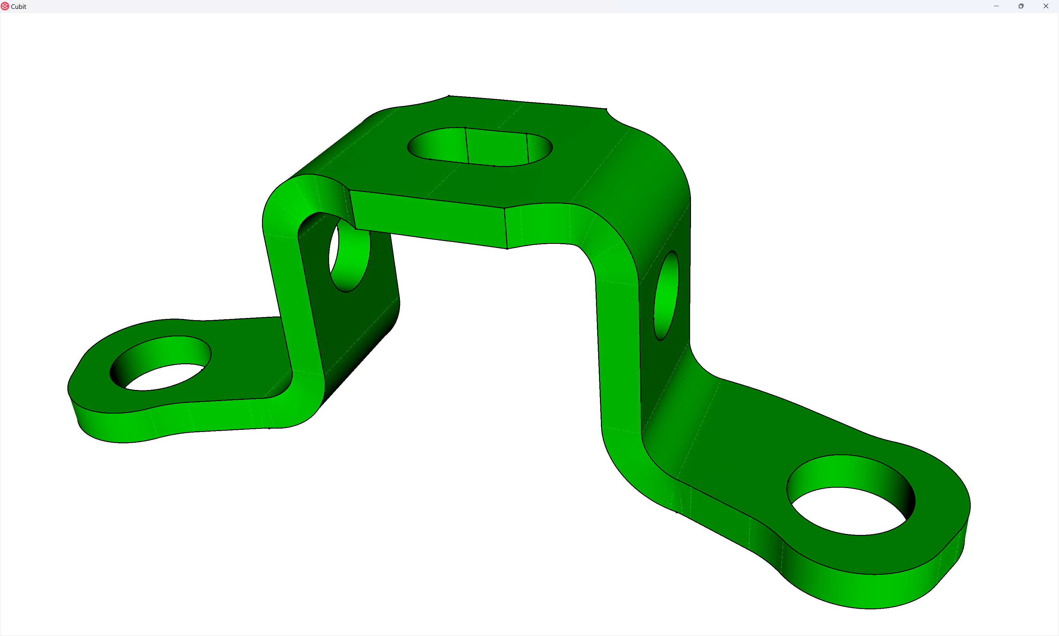
First, let’s turn off the visibility of every volume except those in block 1 (the door link’s block).
## PROCESS BLOCK 1
#!cubit
volume all except in block 1 vis off
zoom reset
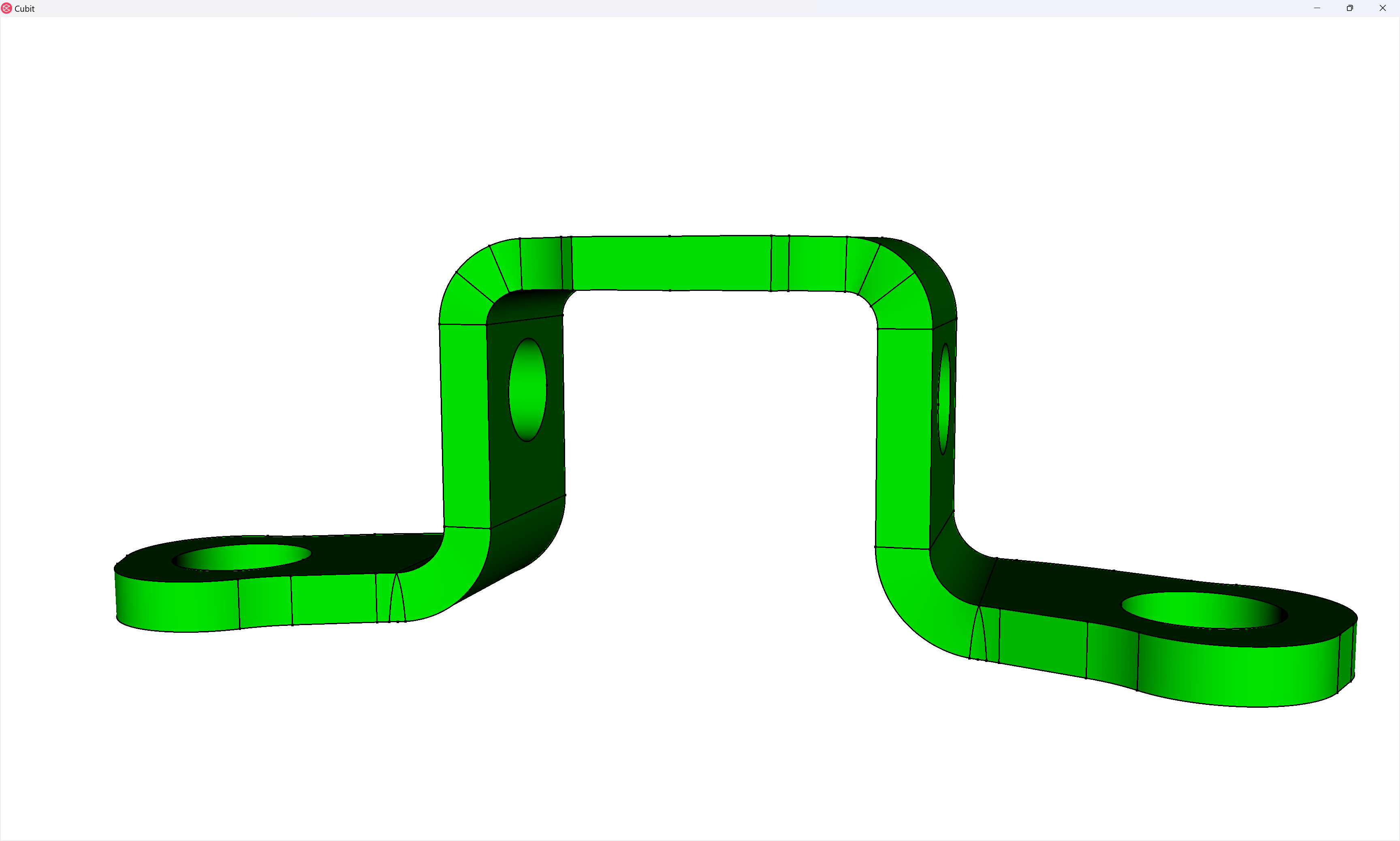
Now, what we’ll notice about this geometry is that it’s almost sweep-meshable, from top to bottom. The reason it’s not are four surfaces that form a triangular shape connecting top-to-bottom – one of which I show below:
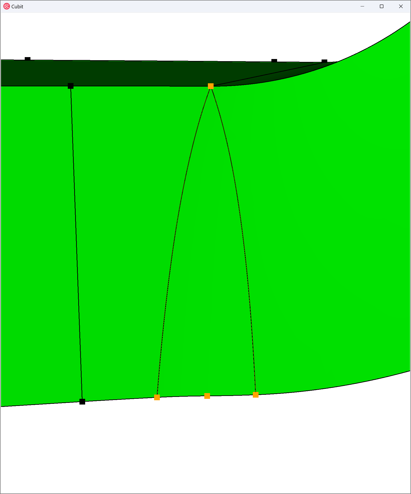
This prohibits a sweep along this path since it would require an unstructured mesh, as demonstrated in this next image, along the sweep direction:
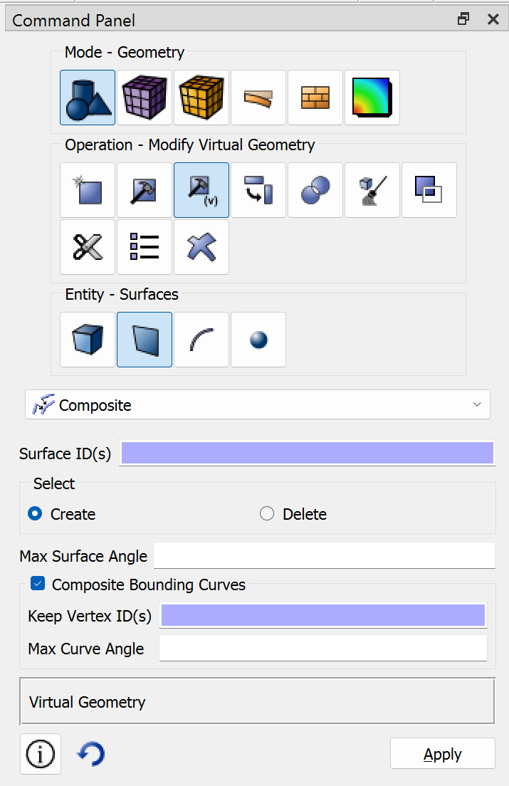
Unstructured meshes along the sweep direction is not supported by Coreform Cubit – the sweep direction must be structured. Fortunately, Coreform Cubit has some tools, namely the ability to create virtual geometry that will allow us to support a structured mesh by ignoring CAD topologies. Here we will create large composite surfaces along the sweep surfaces of the link. First I navigate my command panel to the Composite Surface dialog:
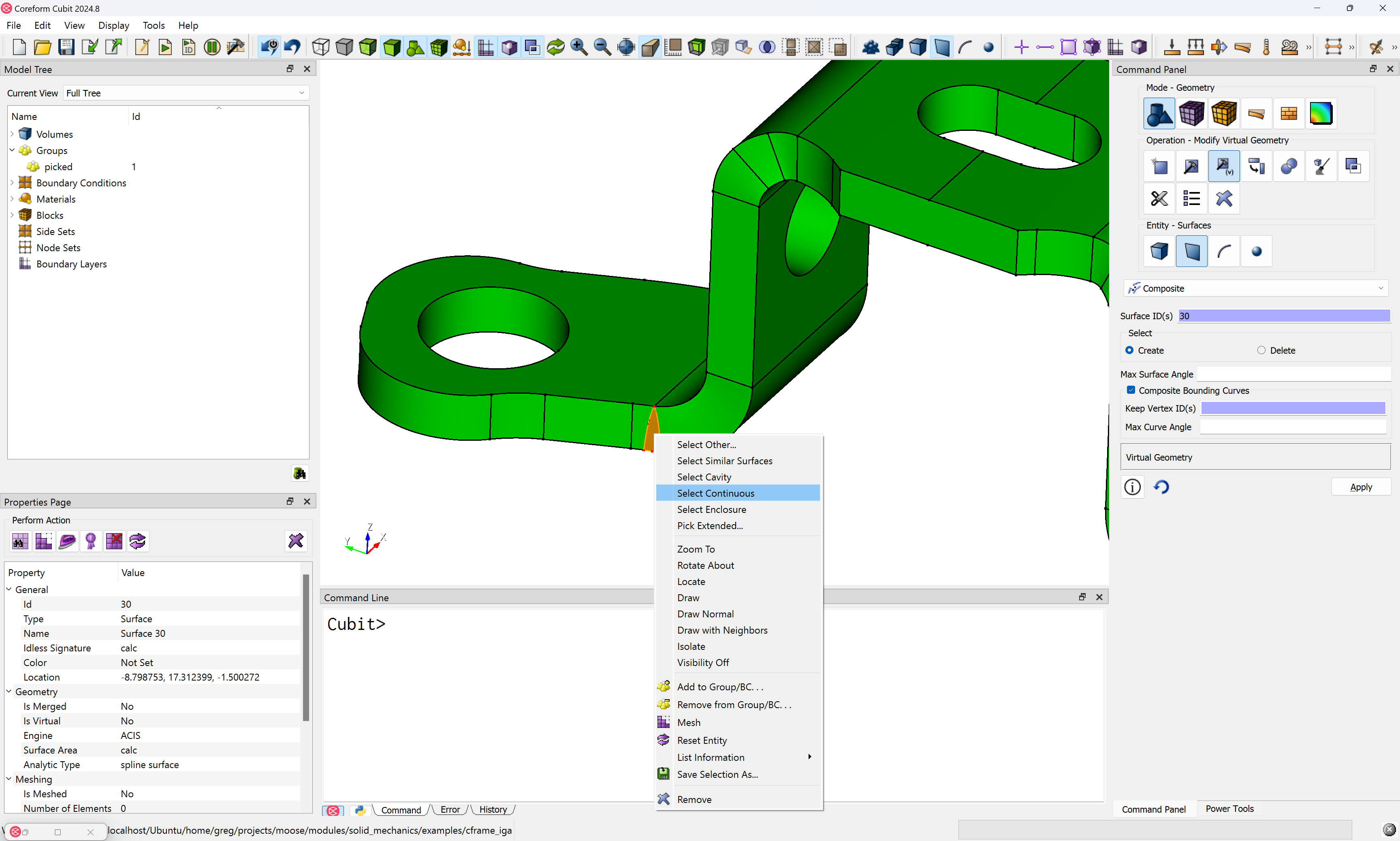
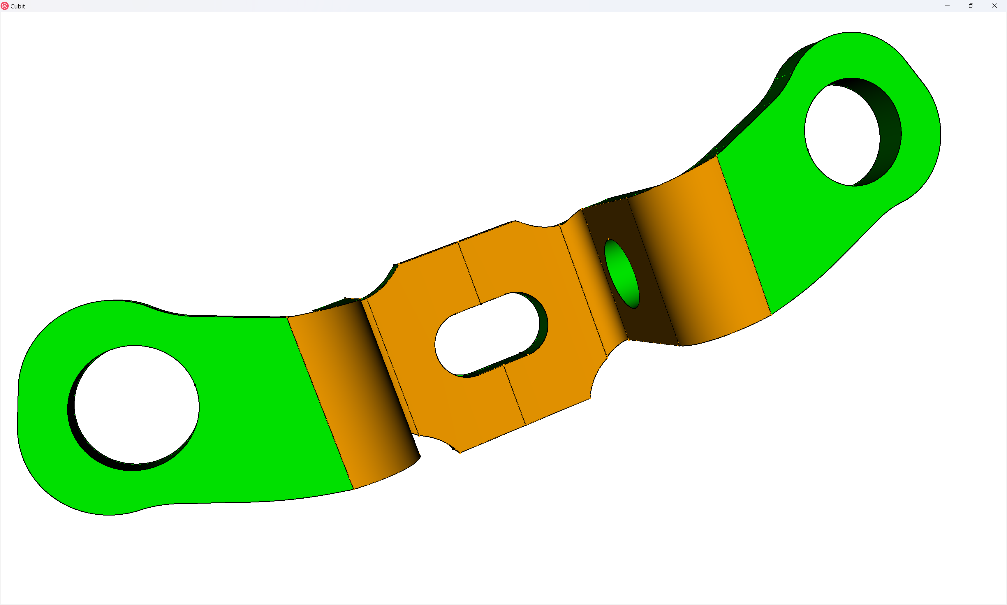
And then within the model window, I select one of the triangular surfaces and right-click on my mouse to bring up additional selection options and choose Select Continuous:
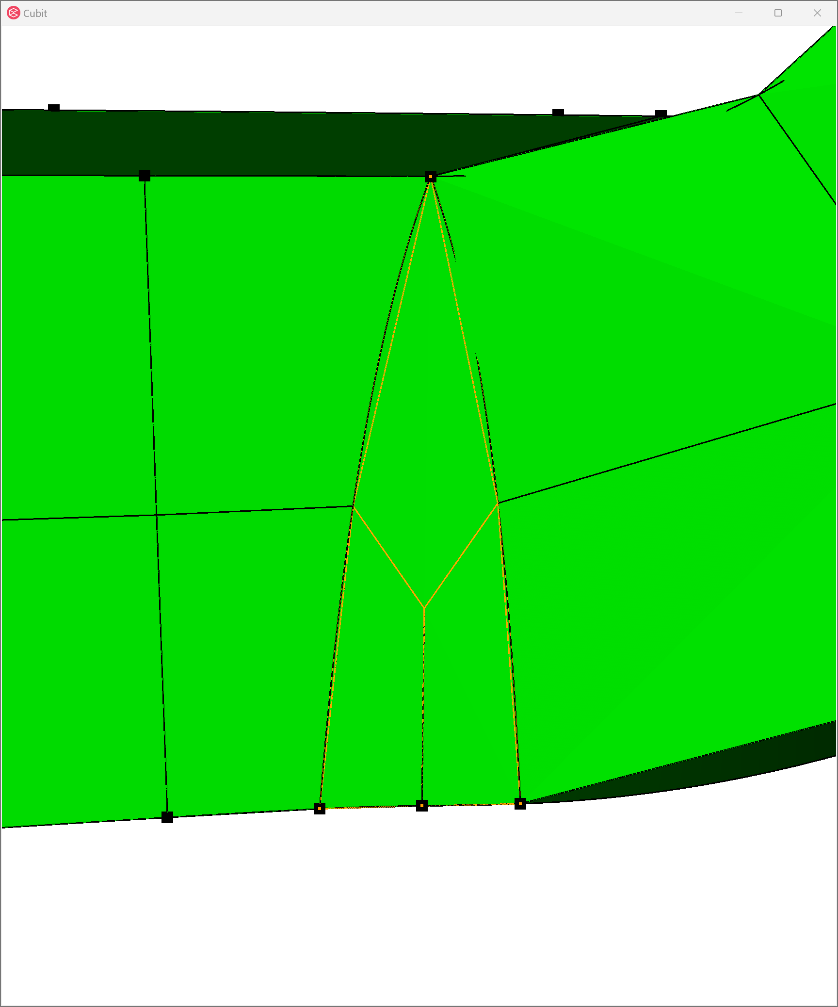
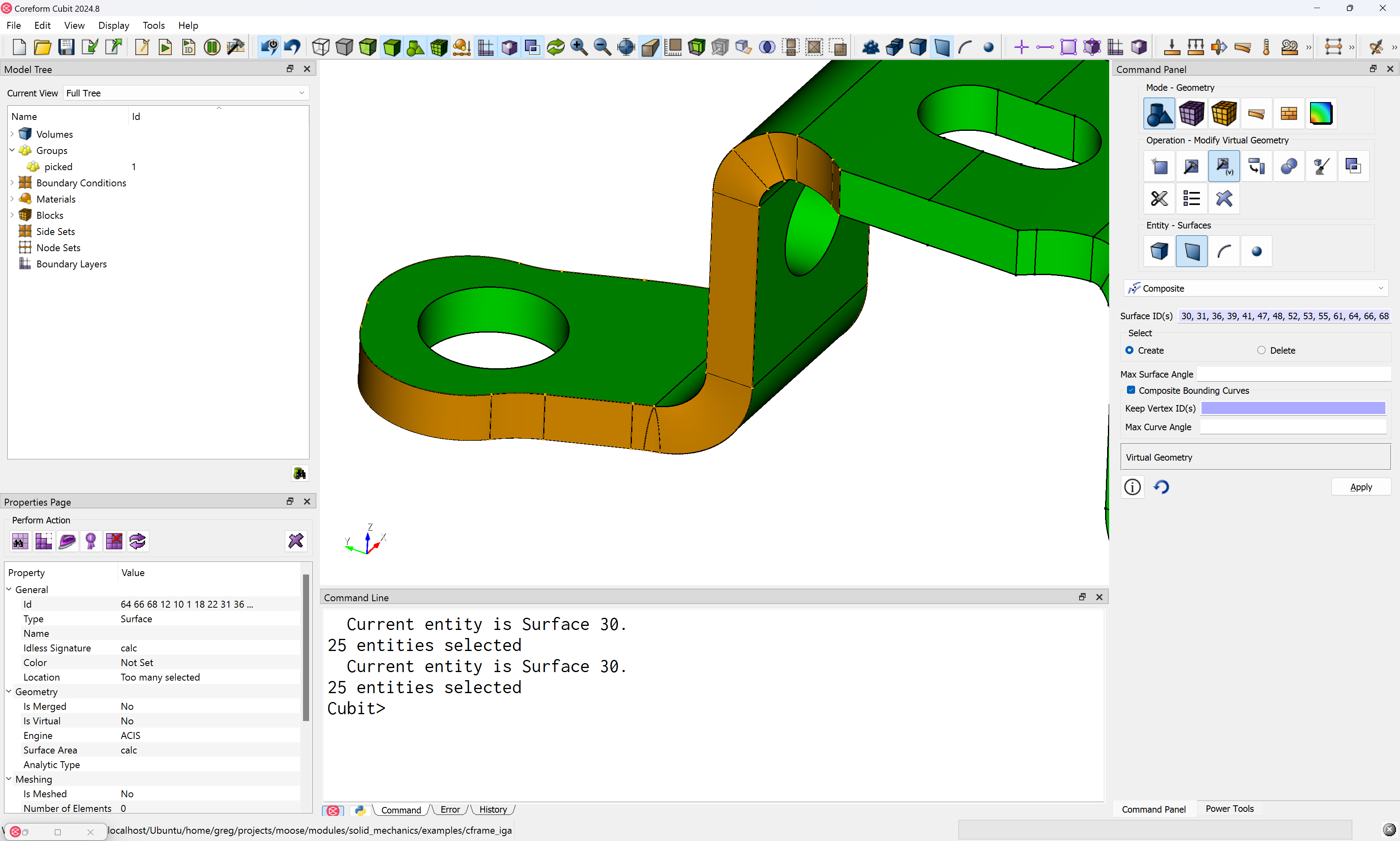
Which will select a large swath of surfaces:
Note the curves that are on the interior of the selected surfaces are now rendered as dashes (---), indicating they’ll be ignored.
We do this same operation on the other side, as well as the top surface. However, we unselect two surfaces from the bottom, as we’ll want to apply boundary conditions on the door link in our simulation – this is an example of how we often need to consider our simulation needs when we’re meshing:
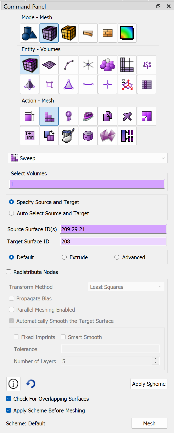
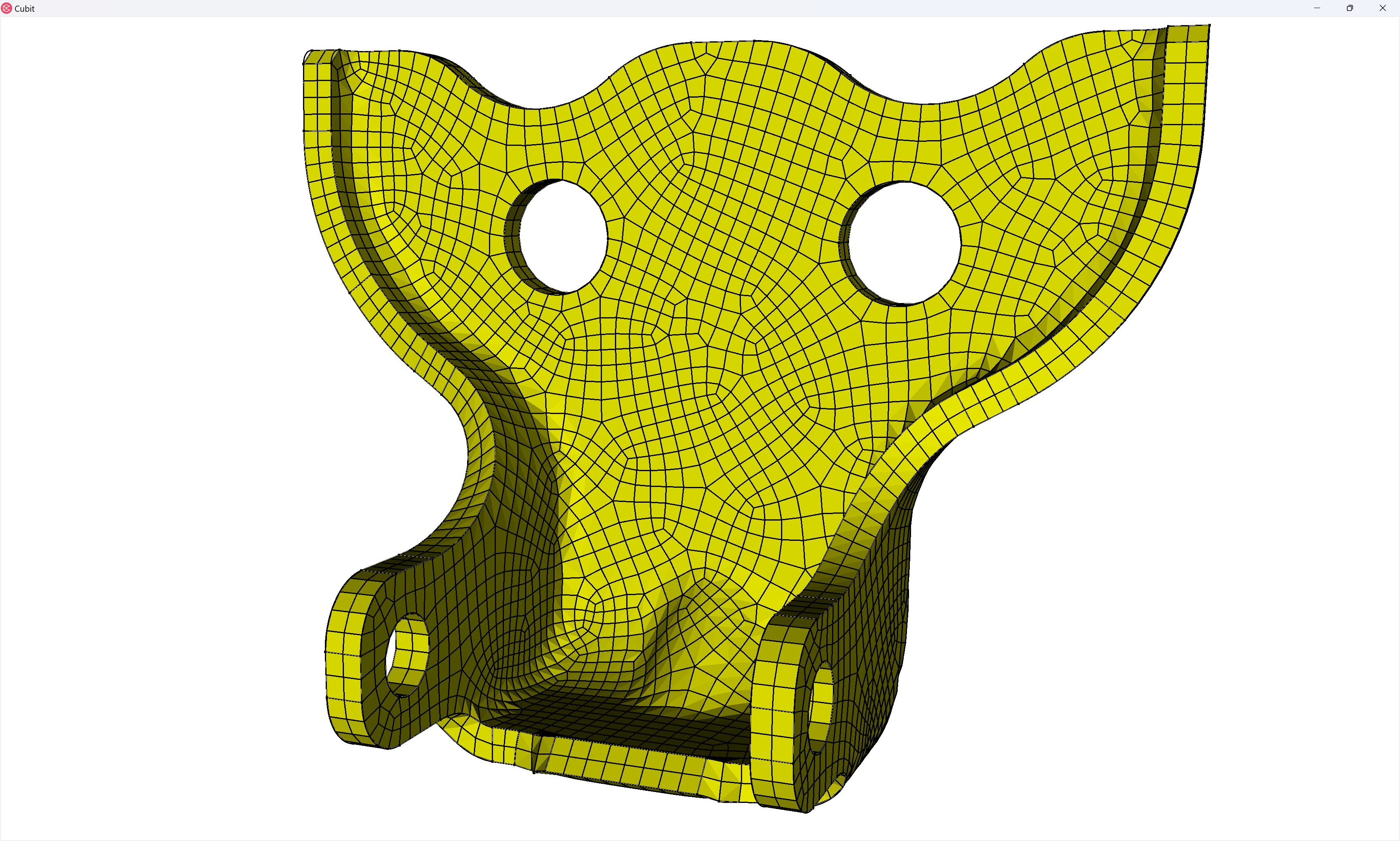
We can then define a many-to-one sweep mesh scheme on this volume, using the underside as the “many” source ids (recall we only partially composited that side to support the boundary conditions):
And choose a mesh size that is moderately fine, using the automatic size calculator:
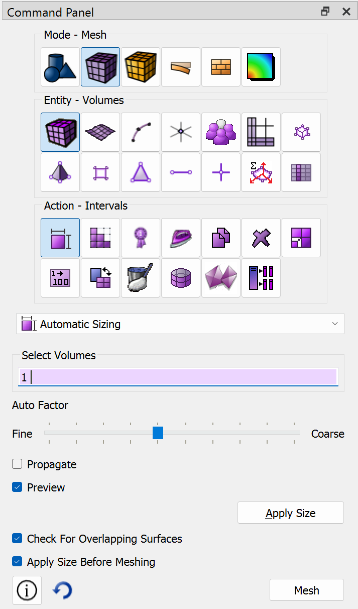
Which produces this mesh:

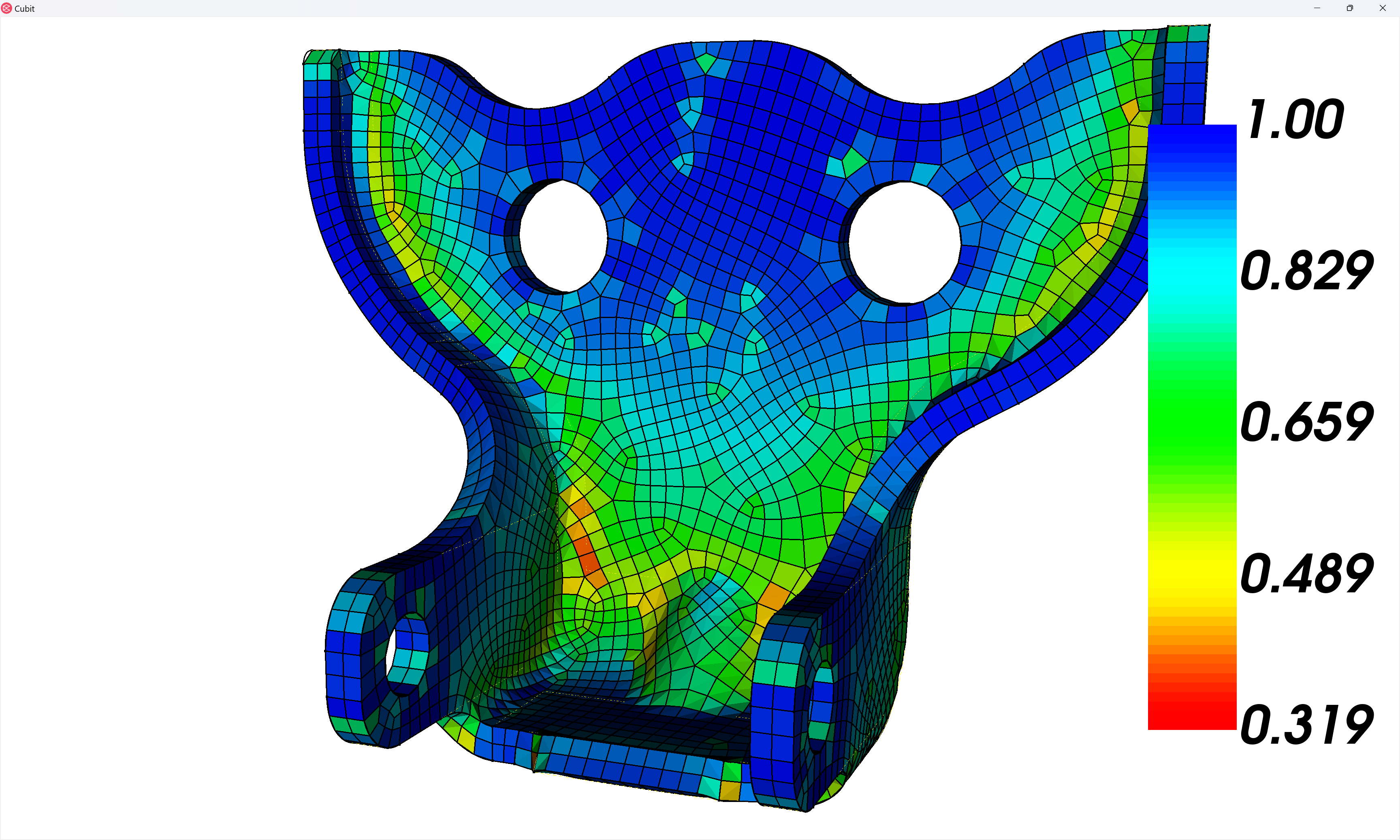
Notice, however, that the element quality is pretty poor along the ∫-shaped portion of the linking surfaces – in fact, the Scaled Jacobian quality metric suggests this initial mesh is effectively unusable for a nonlinear analysis:
quality volume 1 scaled jacobian global draw mesh
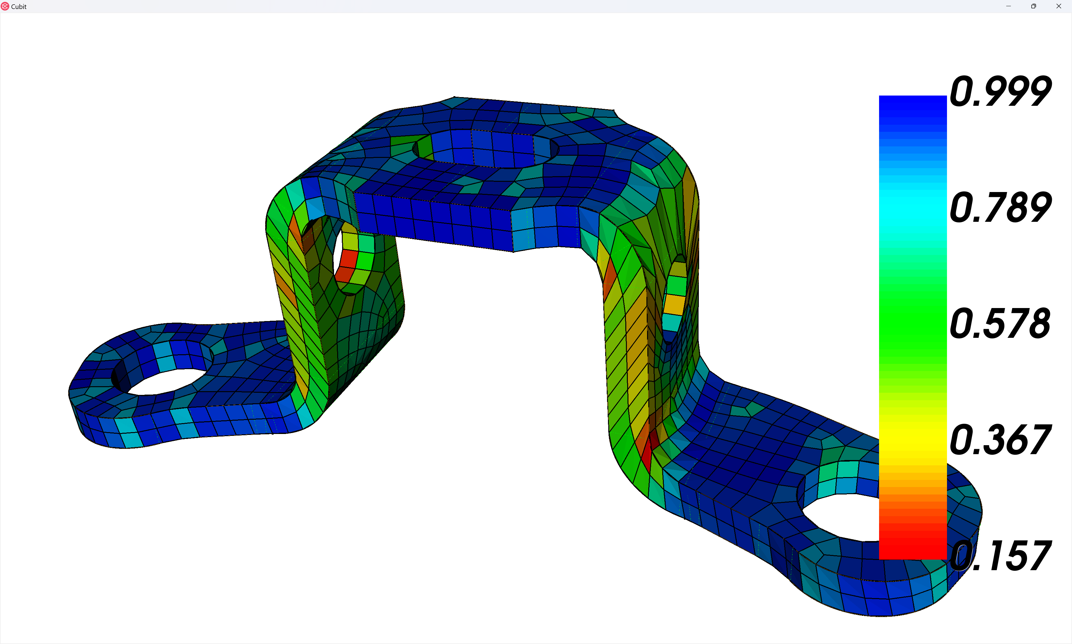
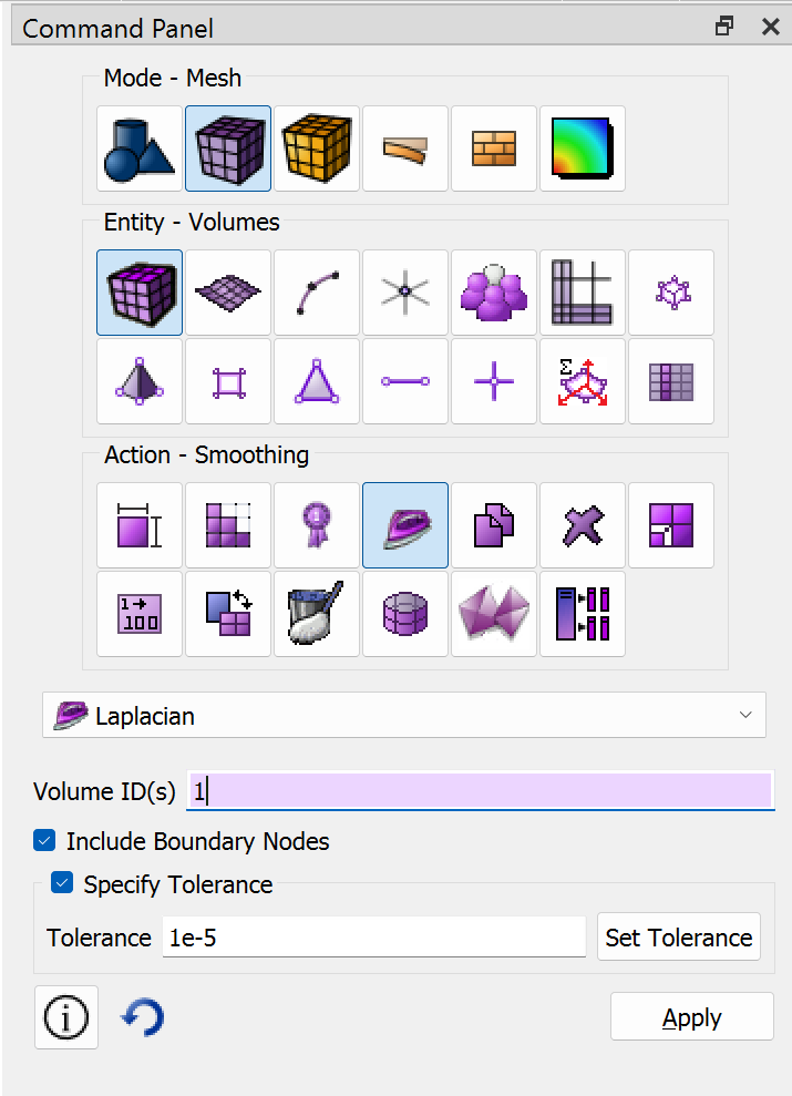
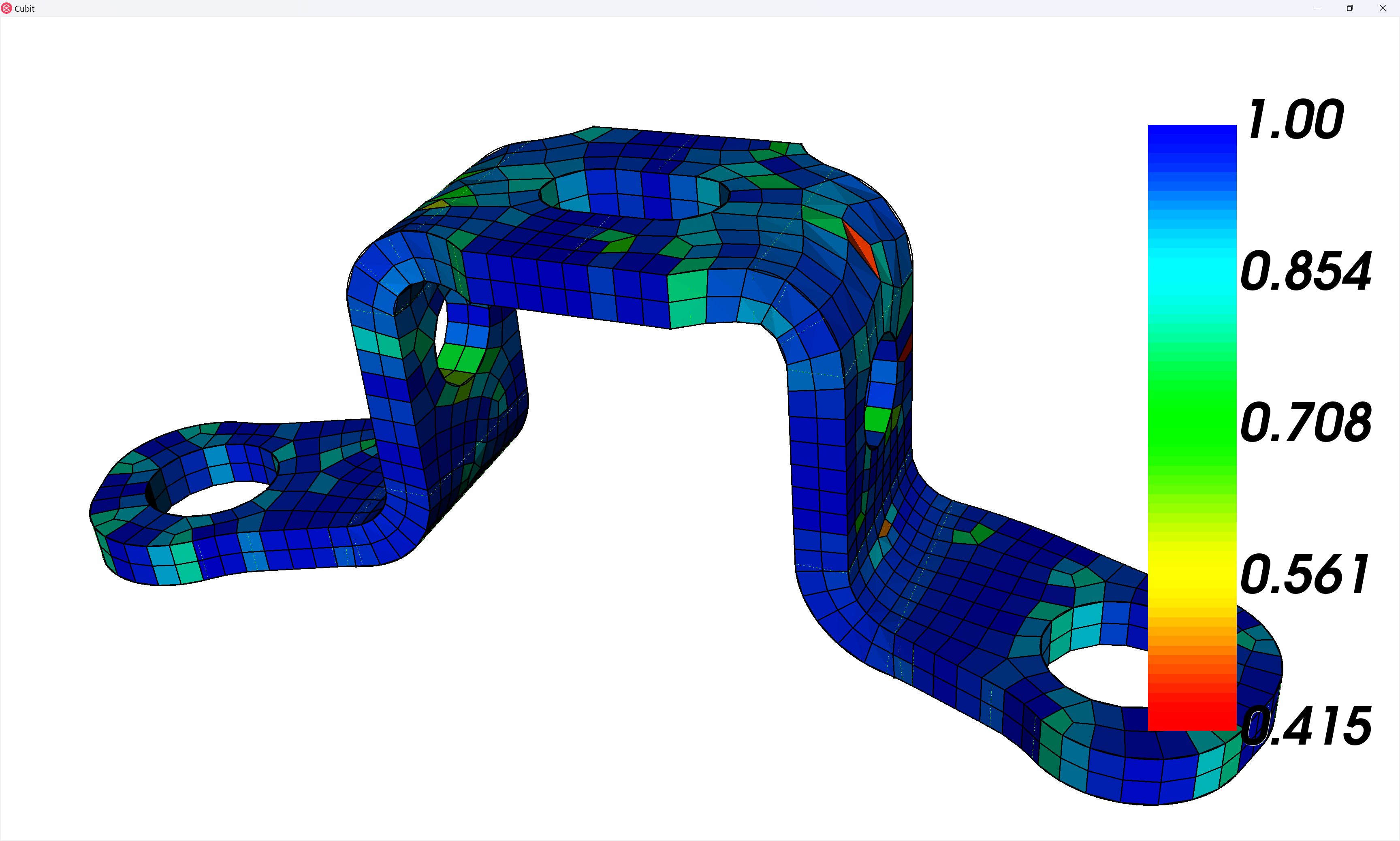
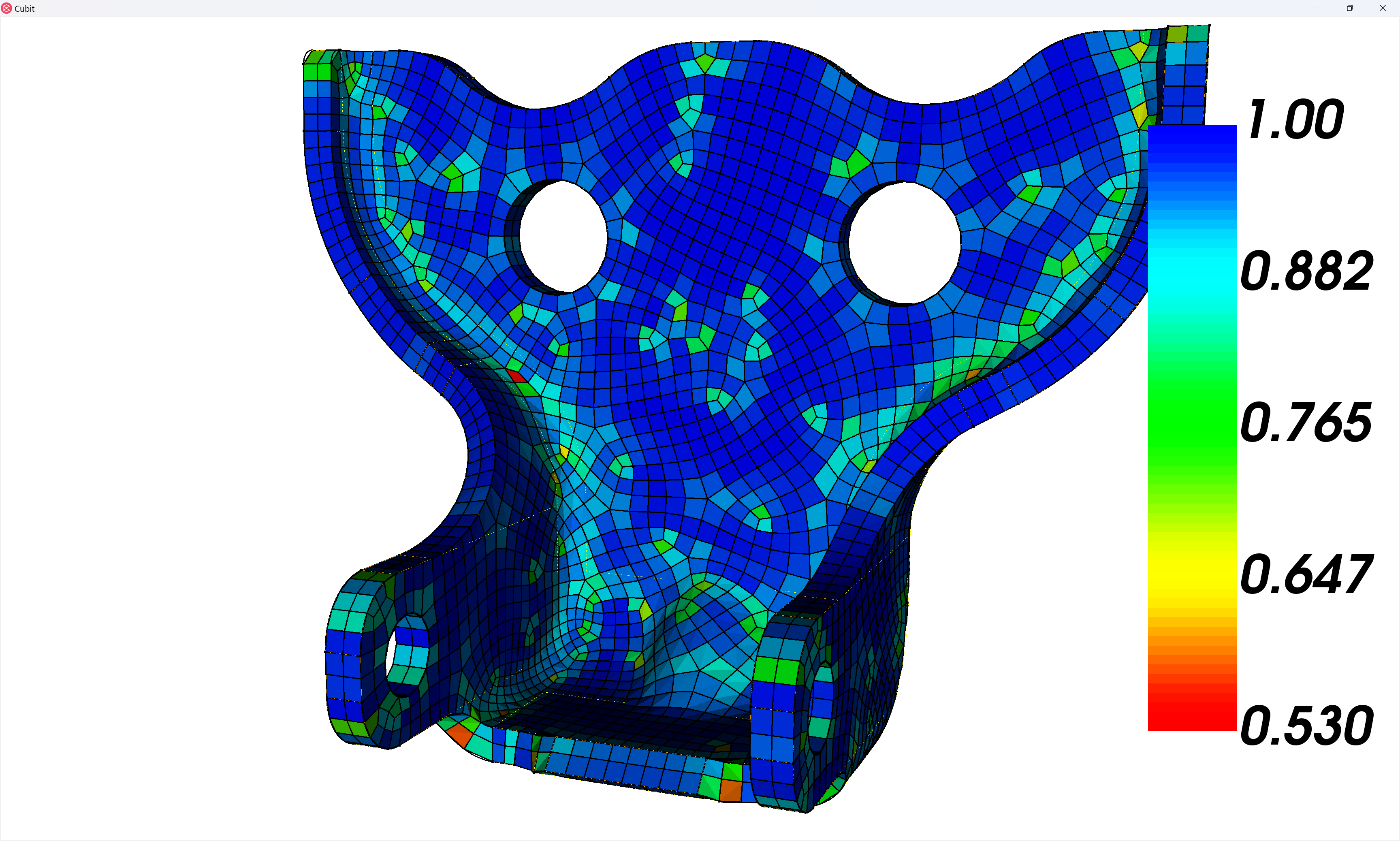
We can use the mesh-smoothing capabilities of Coreform Cubit to improve the mesh quality considerably – note that here I’m using the Laplacian scheme and have chosen to Include Boundary Nodes and Specify Tolerance (be sure to click Set Tolerance). The effect of a tighter tolerance is the same as running the smoother multiple times at the original tolerance.
Meshing the door hinge
Now we move onto the door hinge, again setting the visibility for every other volume to off:
## PROCESS BLOCK 2
volume in block 2 vis on
volume all except in block 2 vis off
zoom reset

Again our overall strategy is to define a sweep mesh between the inner and outer surfaces, using compositing on both. Since there are no unsweepable topologies on the linking surfaces we don’t need to composite them:
Because we’ve left the linking curves in the model, the initial mesh does have pretty good quality even on the ∫-shaped regions:
Even so, the Laplacian smoother improves the quality considerably:
Meshing the door pin
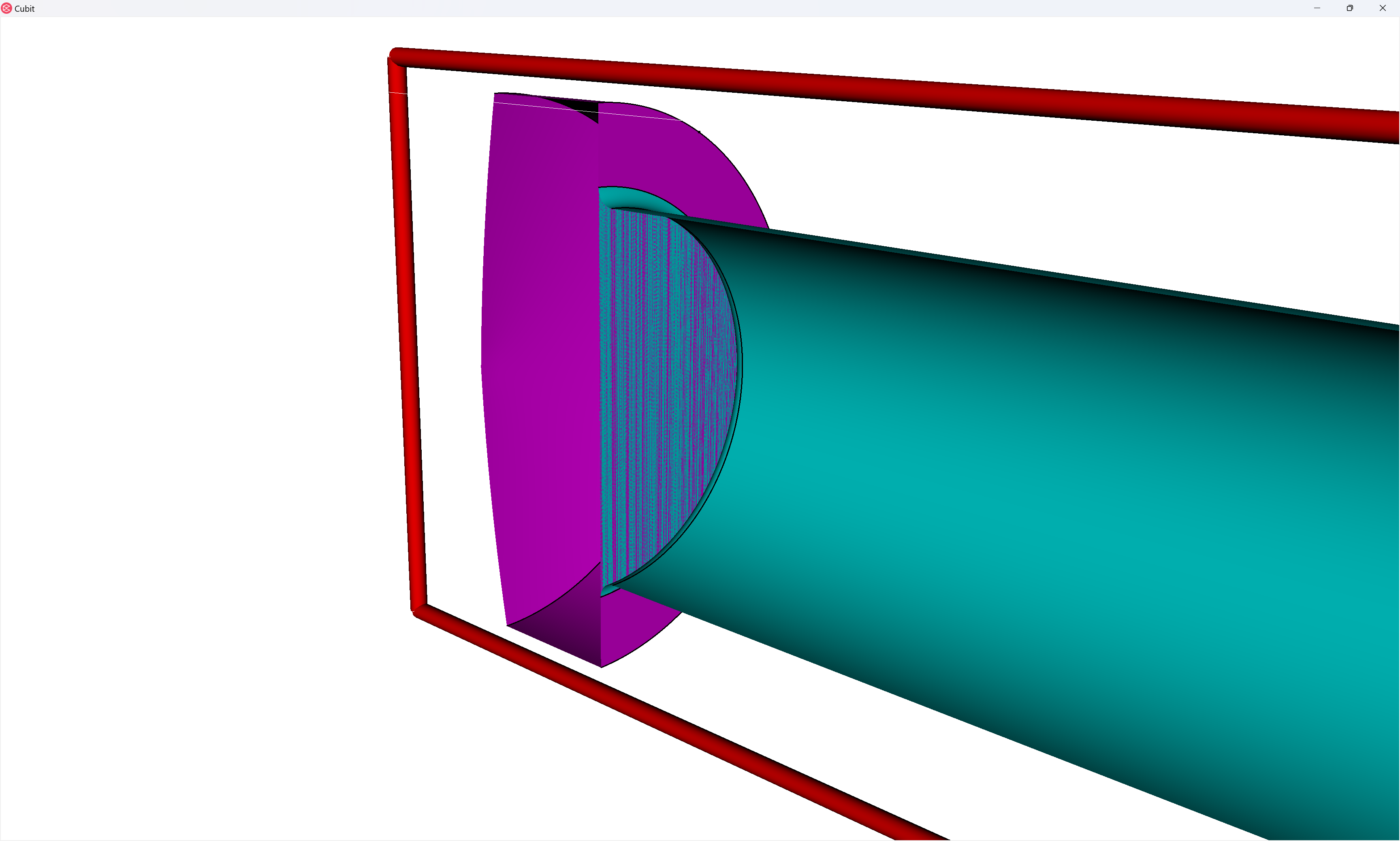
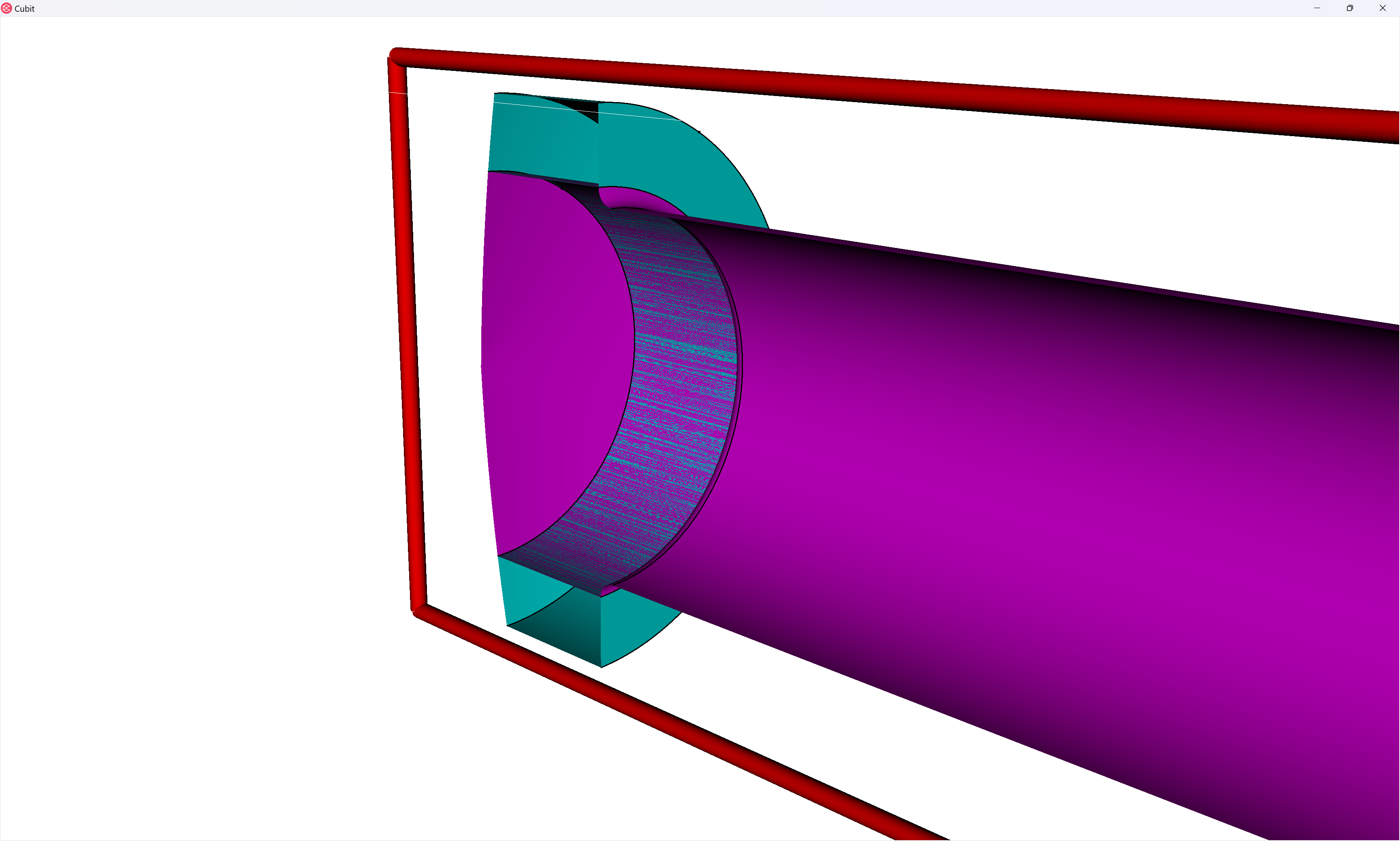
Unlike the first two parts, which were thin parts with obvious sweep directions, we’ll need to partition the door pin to make it meshable.

As we perform our webcuts, we’ll try to make sure we only apply webcuts that are produce nearly-orthogonal interface surfaces. For example:
BAD
This approach will create a tangency at the fillet which will lead to bad meshes

GOOD
This approach will create a 90-degree interface next to the fillet
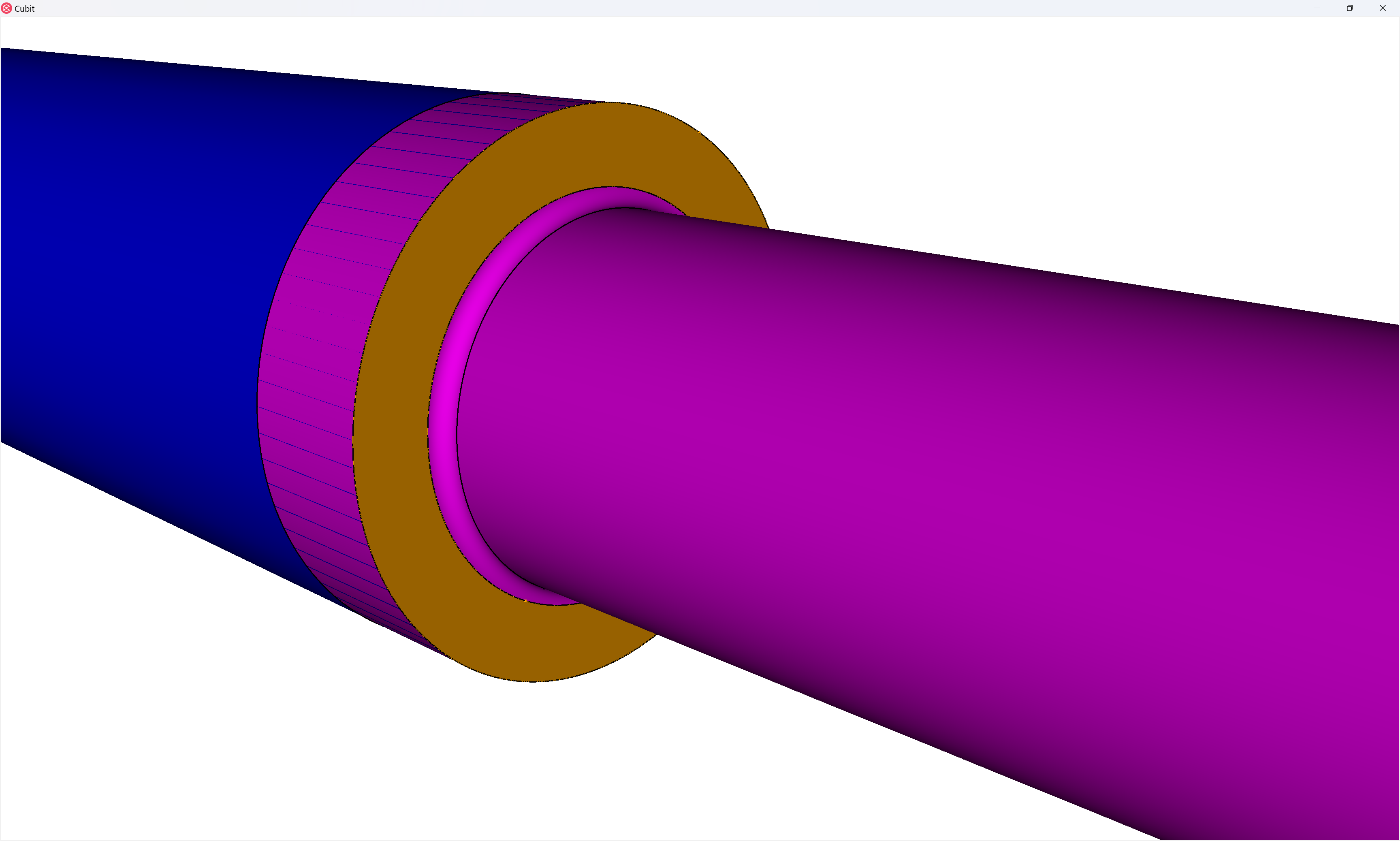
Let’s go ahead and do that second webcut on both sides of the pin:
And here we see the value of assigning our blocks prior to meshing: the block automatically updates and adds the new volume(s) from each webcut to the block.
Cubit>list vol in block 3 ids
  The 3 entity ids are: 3 to 5.
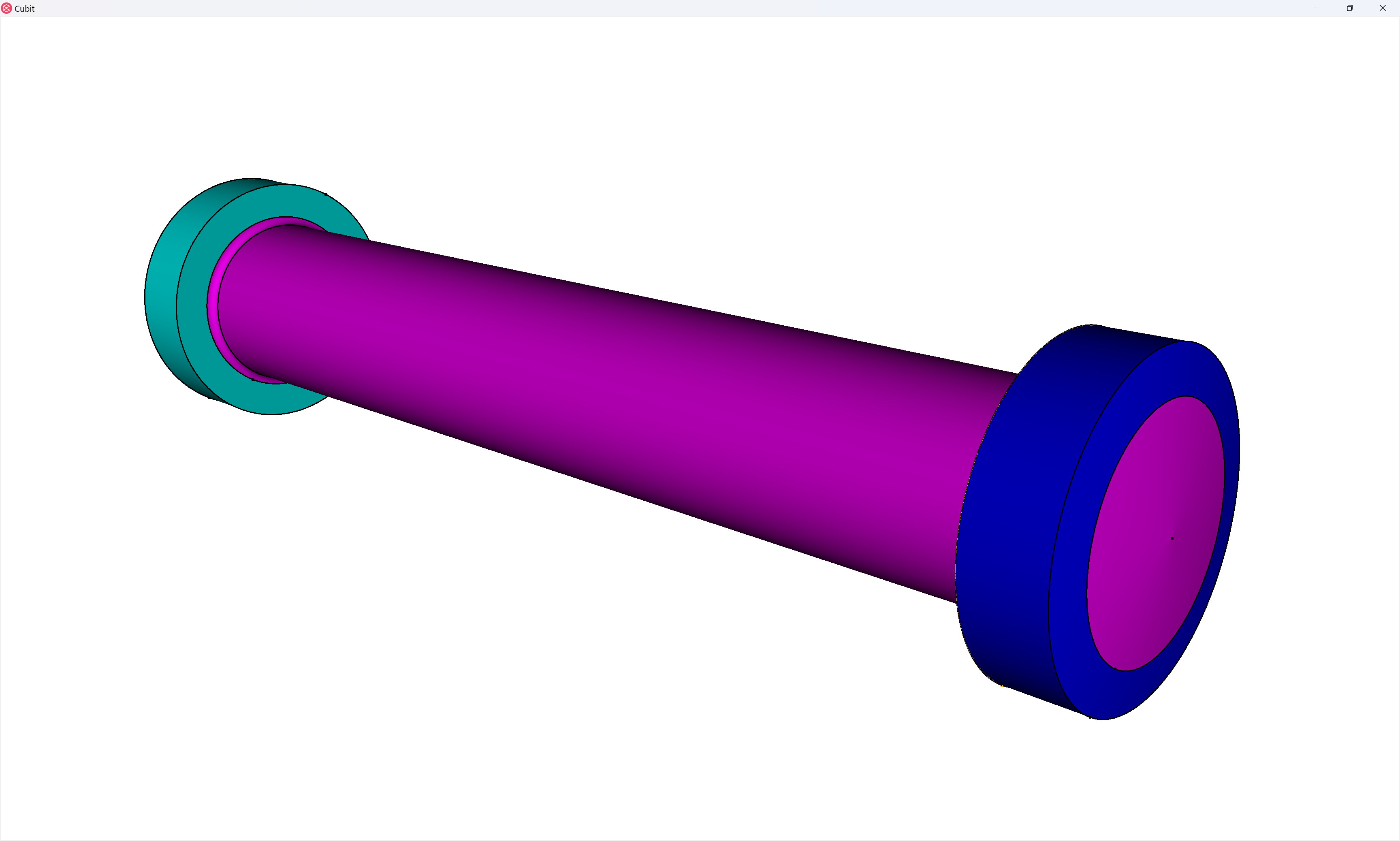
Next we cut the top of the fillets, using the loop webcut:
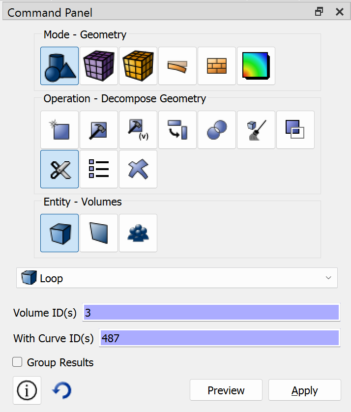
webcut volume 3 with loop curve 487
webcut volume 3 with loop curve 488
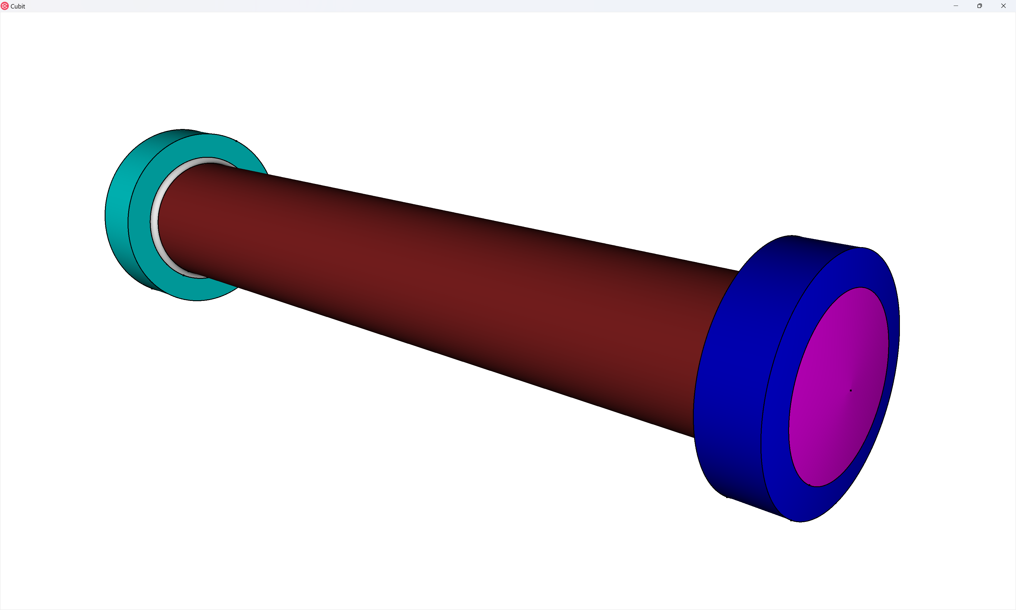
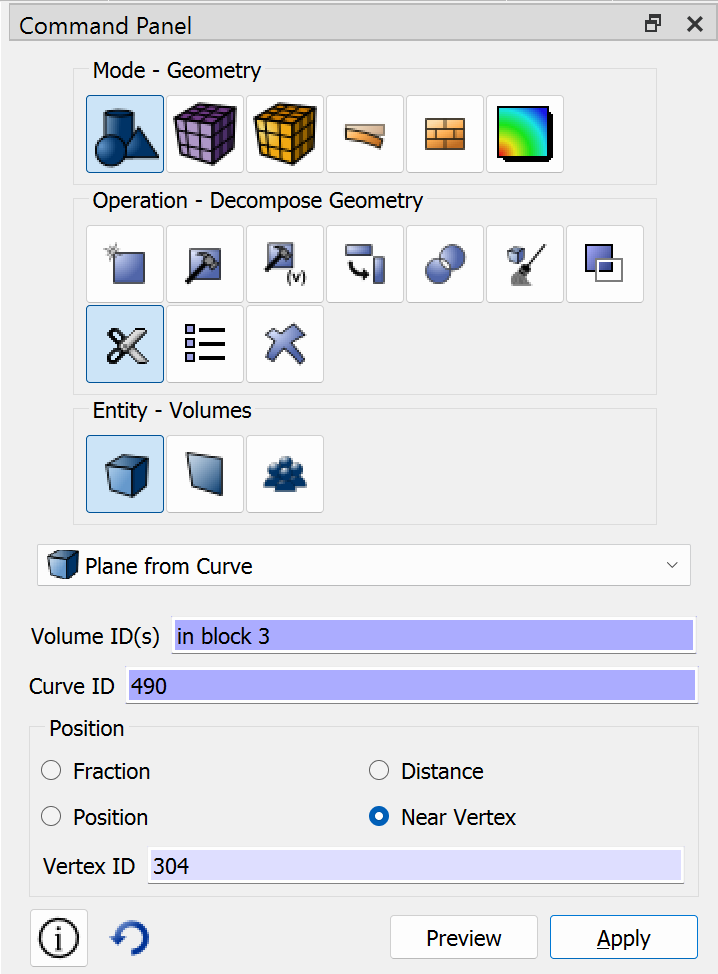
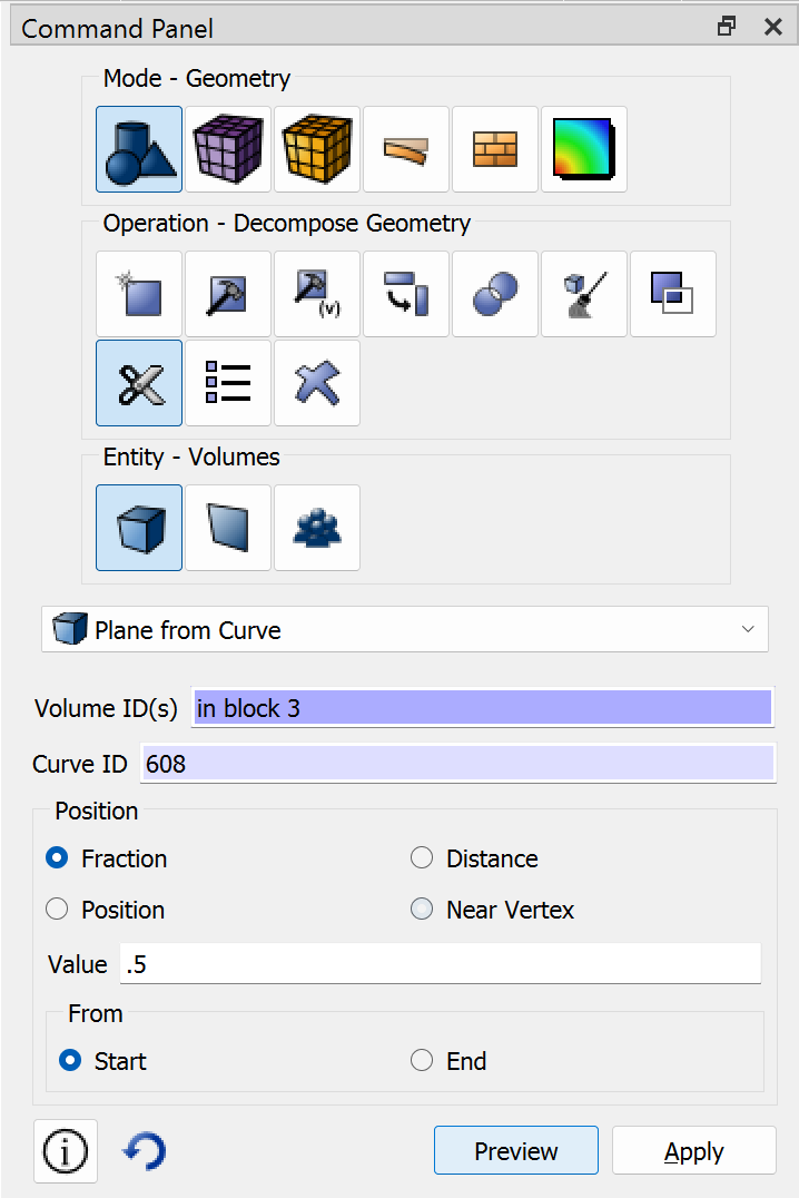
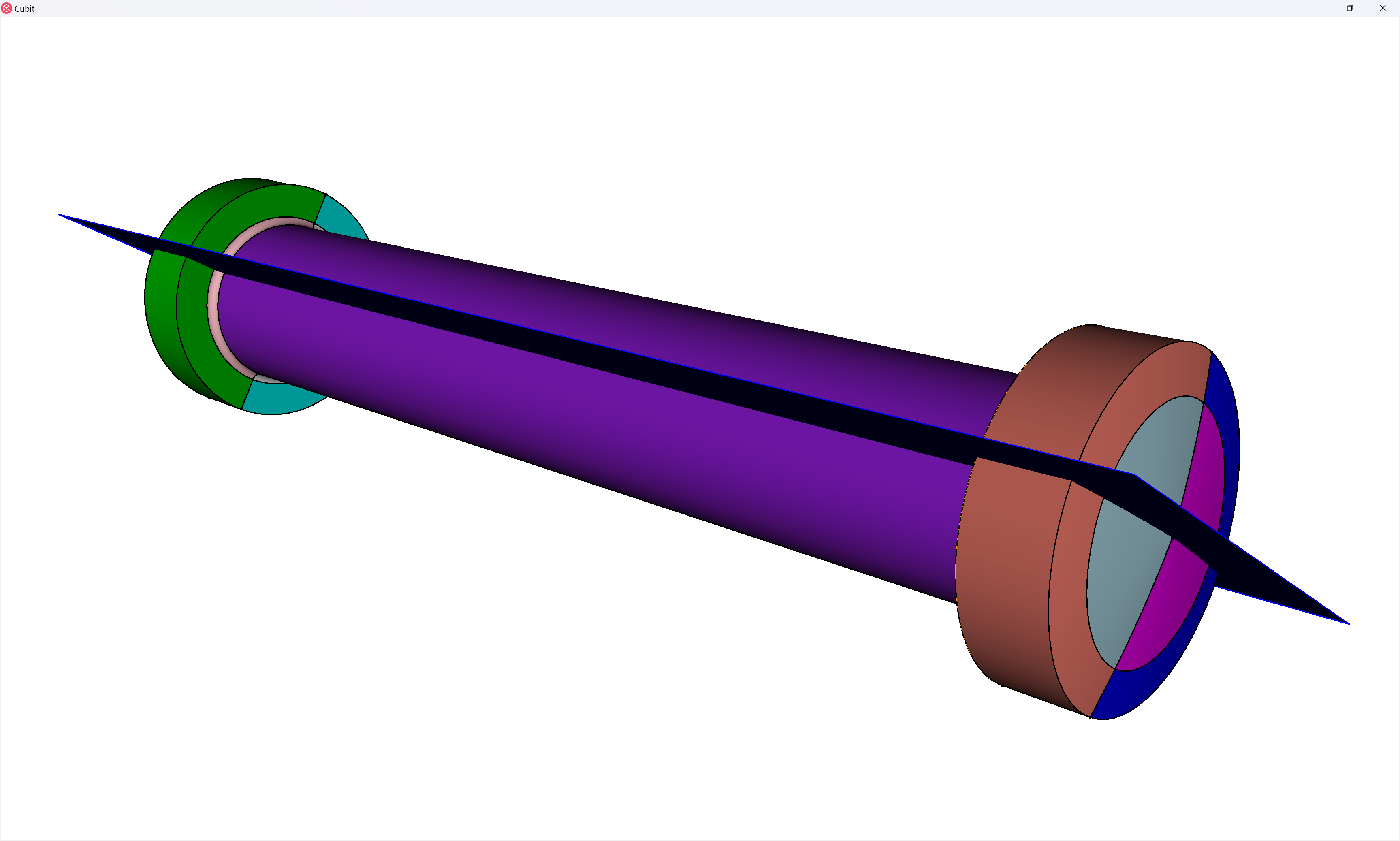
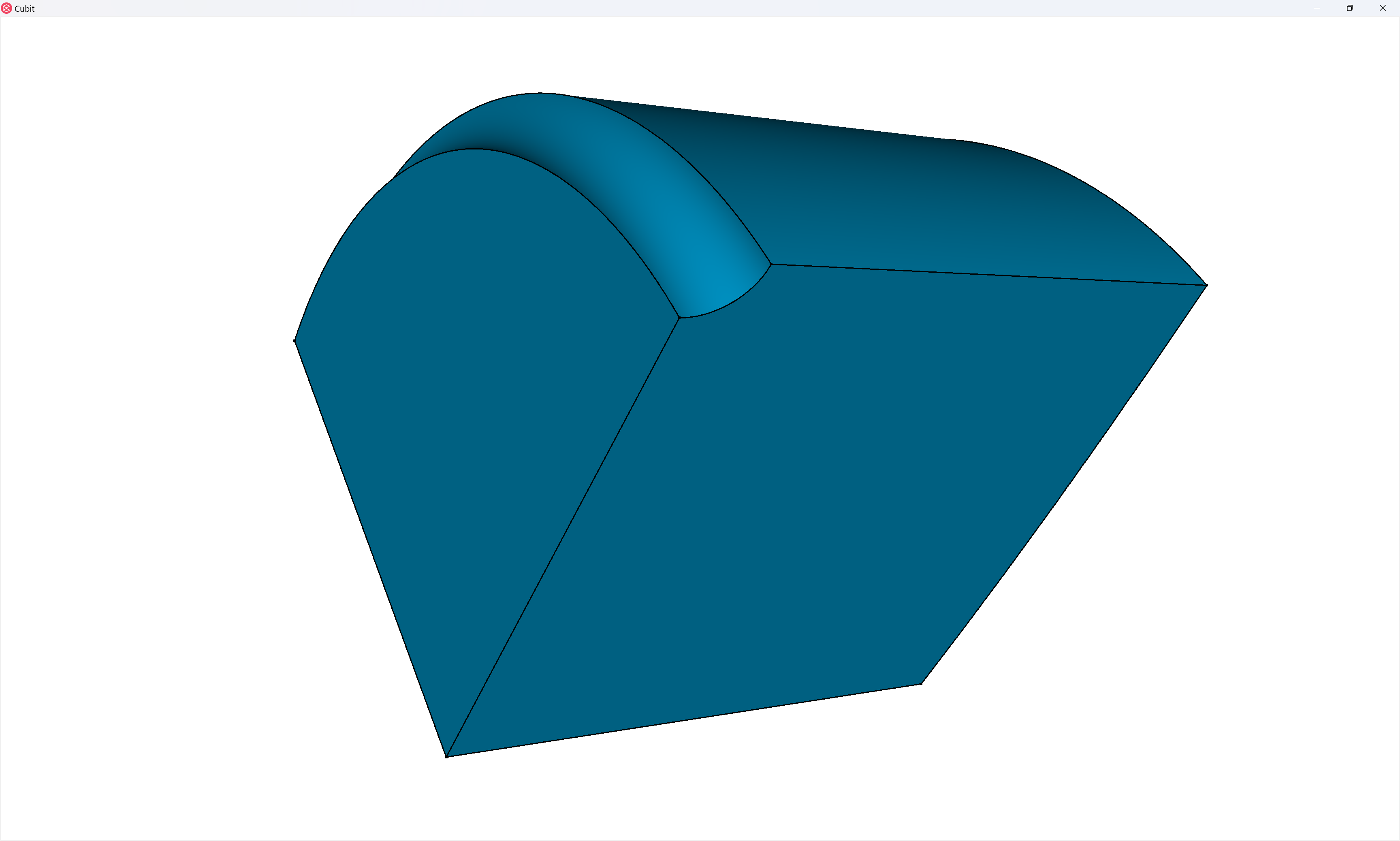
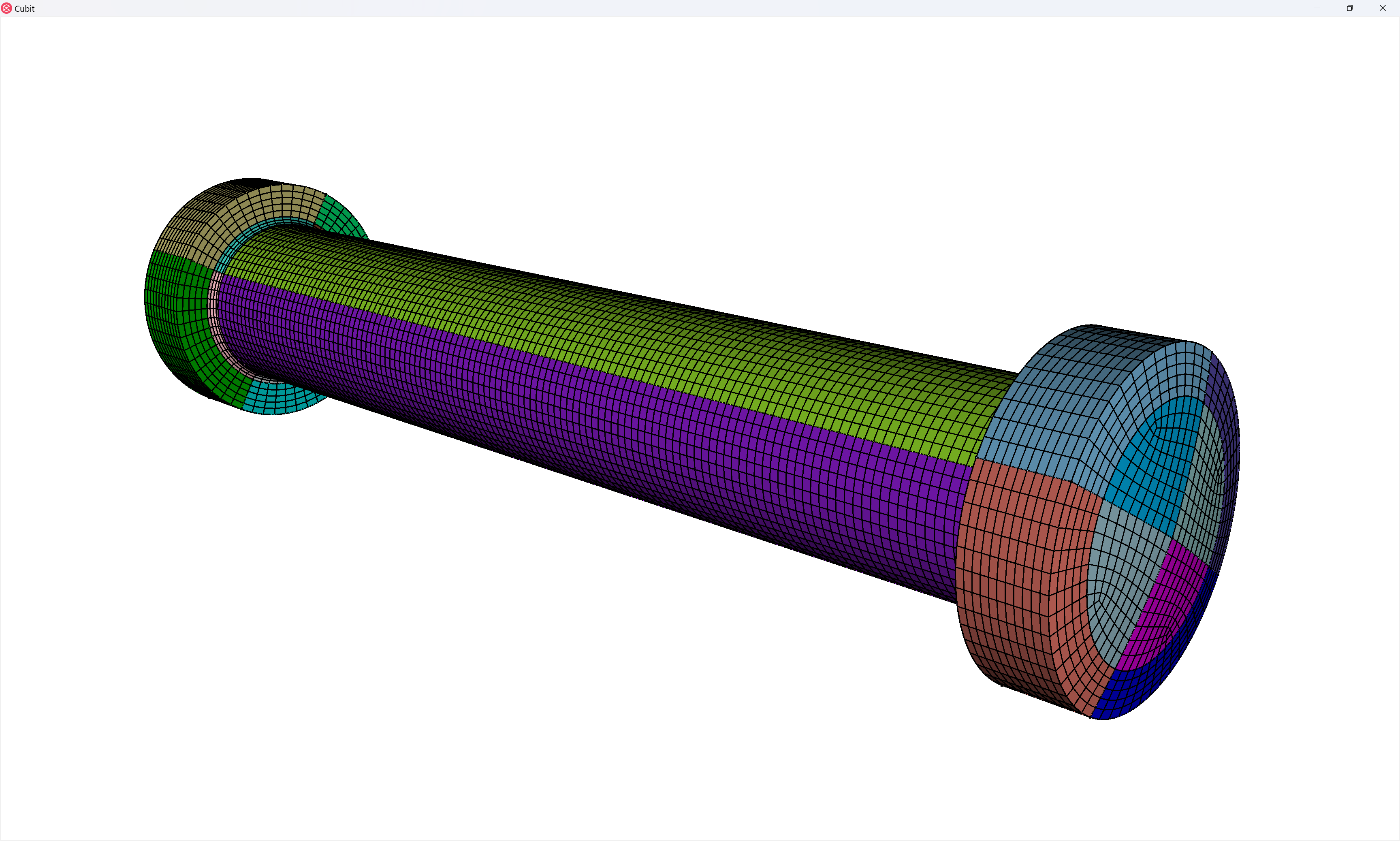
And finally, we cut with planes that are normal to the the circular curves, cutting the pin into fourths:
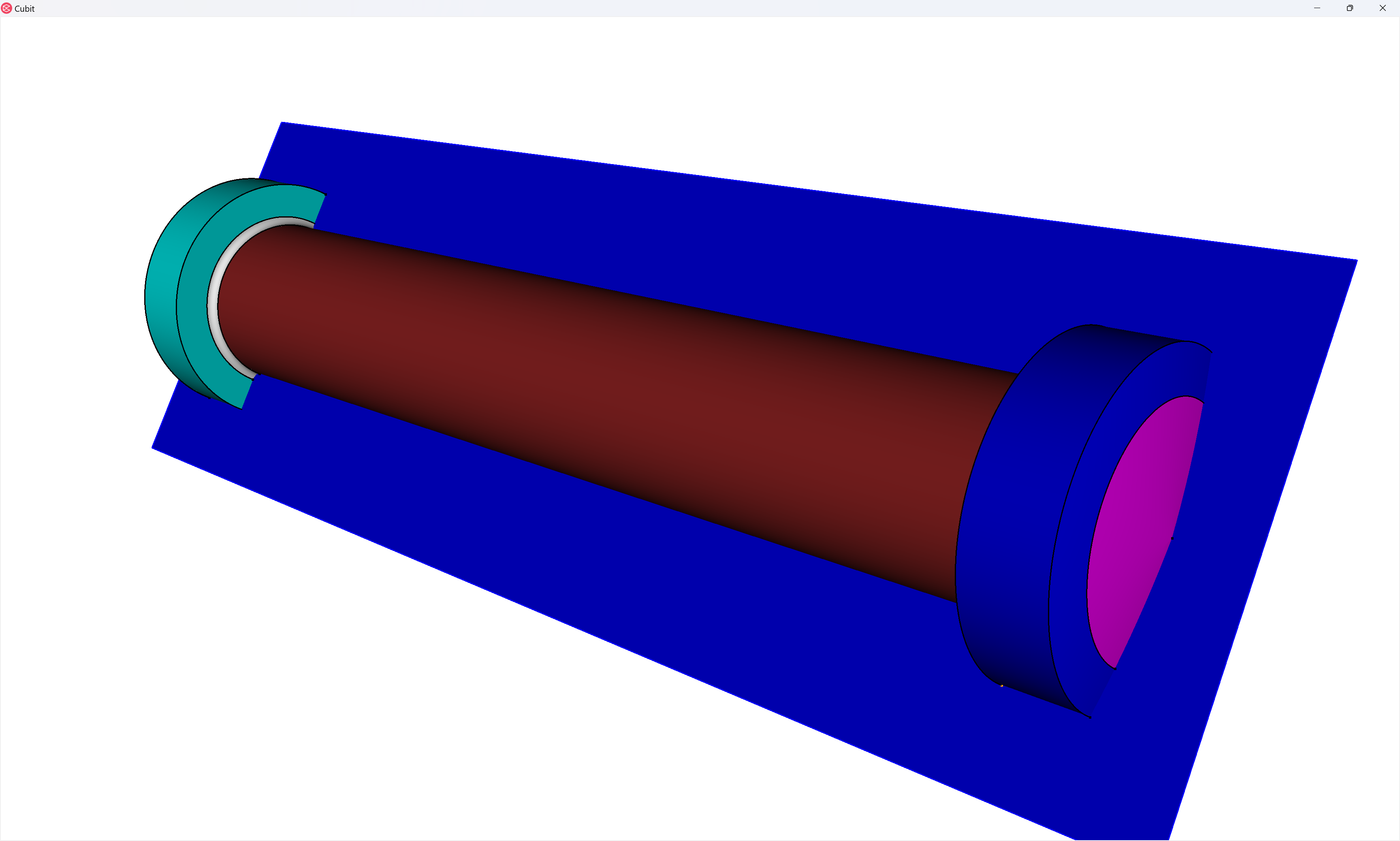
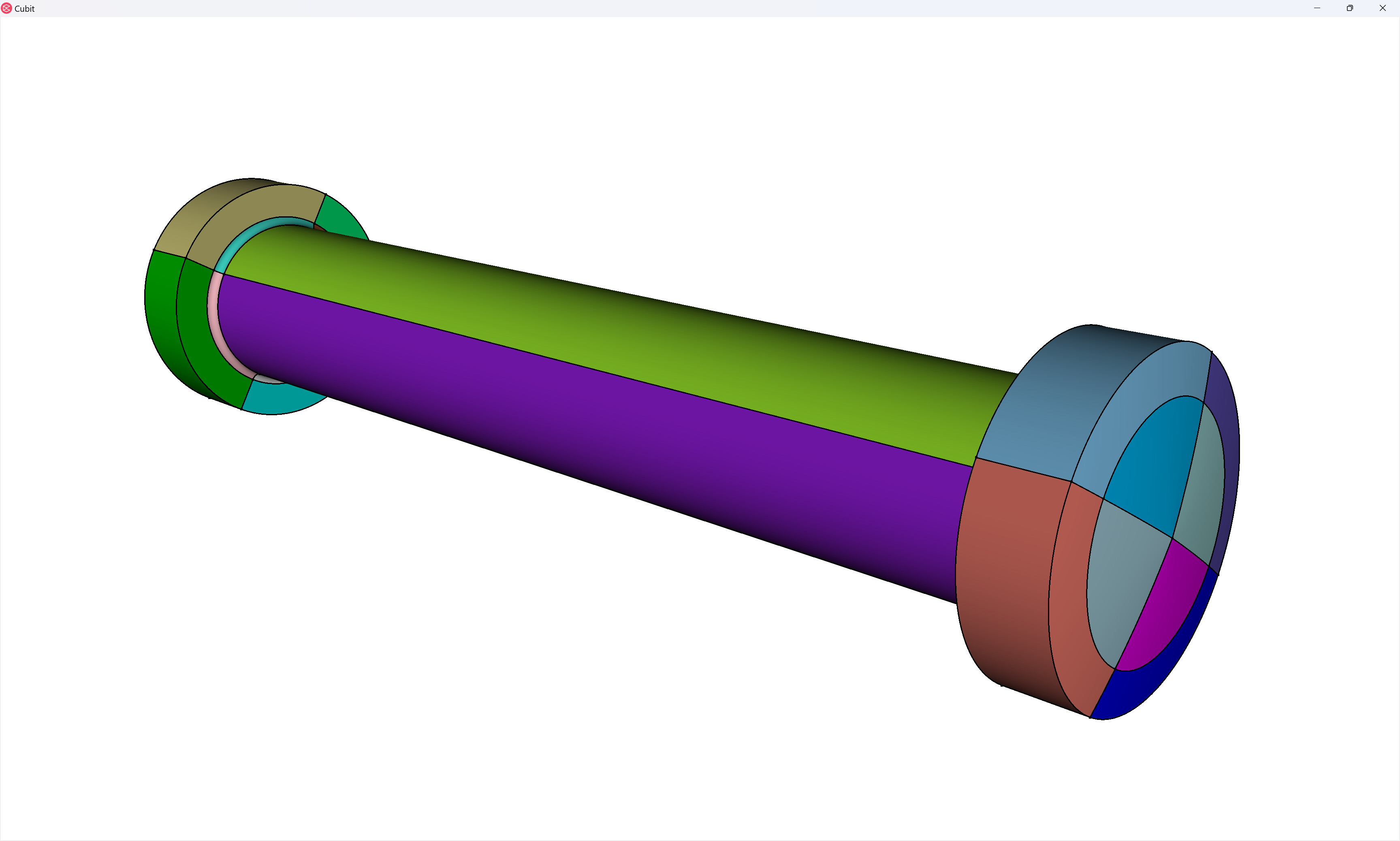
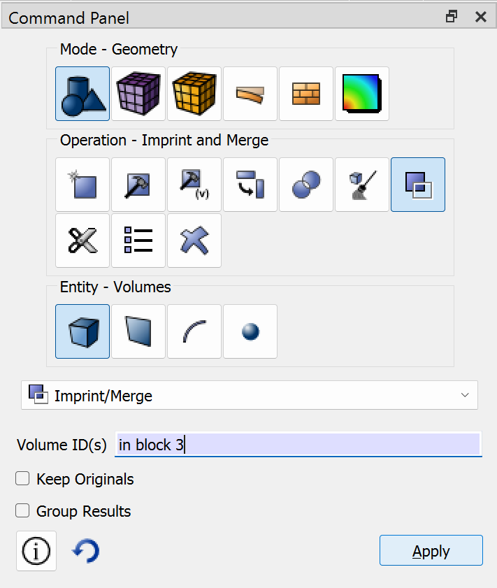
As a final step, we will use the imprint and merge operations to connect the volumes of the partitioned pin so that we’ll get a contiguous mesh. Note that in this case I know that I’ve partitioned the geometry so that the imprint operation isn’t necessary, but it’s a good habit to do it anyways. Again, I’m going to use extended parsing to simplify entity selection:
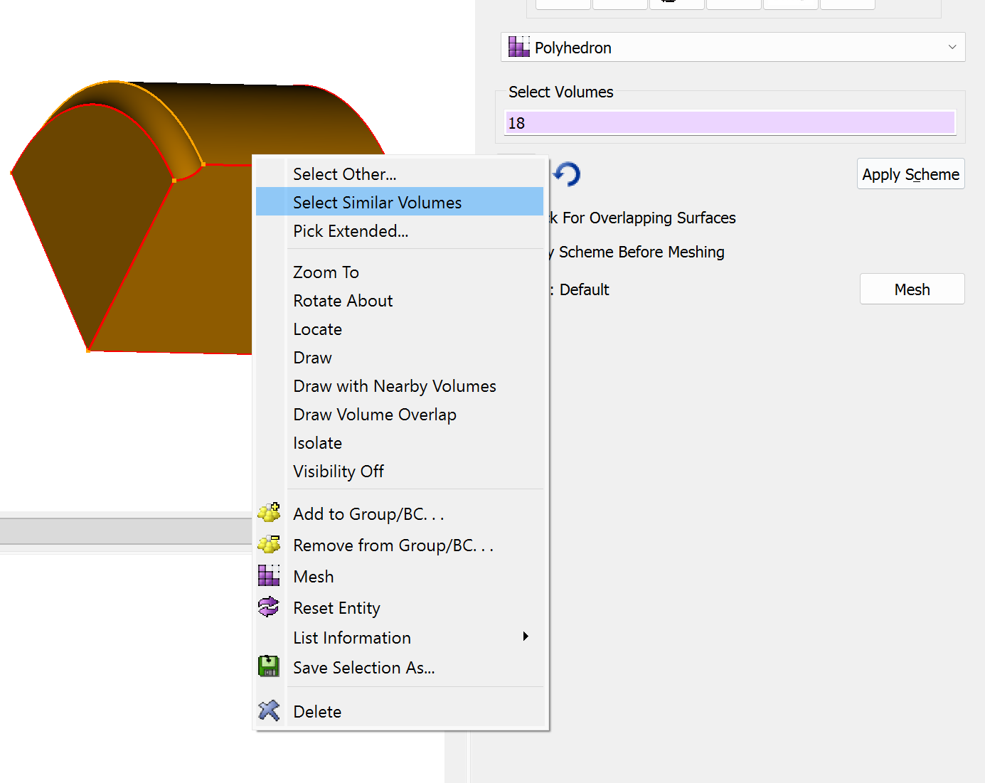
We now proceed to mesh-generation on the pin. First, note that the eight volumes connected to the fillets have a shape that is conducive to the polyhedron mesh scheme:
We can more easily select each of these volumes by selecting one of them, and then right-click and choose the Select Similar Volumes option:

While the rest of the volumes in the pin are automatically meshable by Coreform Cubit:
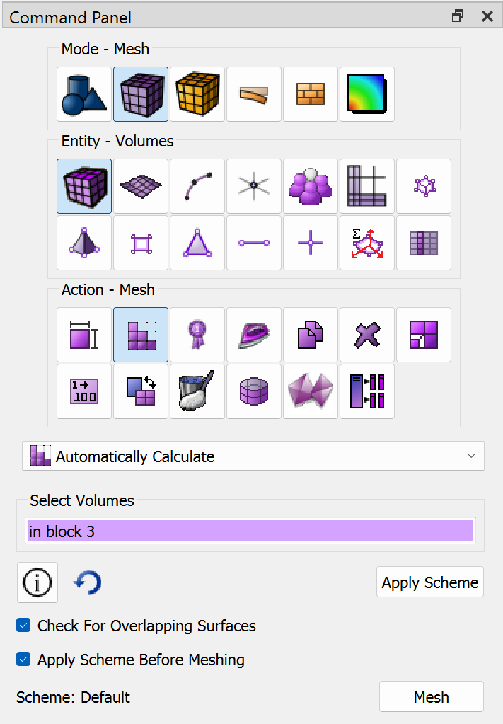
TIP: When using polyhedron meshes you should generally assign the polyhedron scheme last, but then mesh the polyhedron volumes first.
volume in block 3 size auto factor 3
volume in block 3 scheme auto
volume 21 3 6 13 16 11 8 18  scheme polyhedron
mesh volume 21 3 6 13 16 11 8 18
mesh vol in block 3
Reviewing
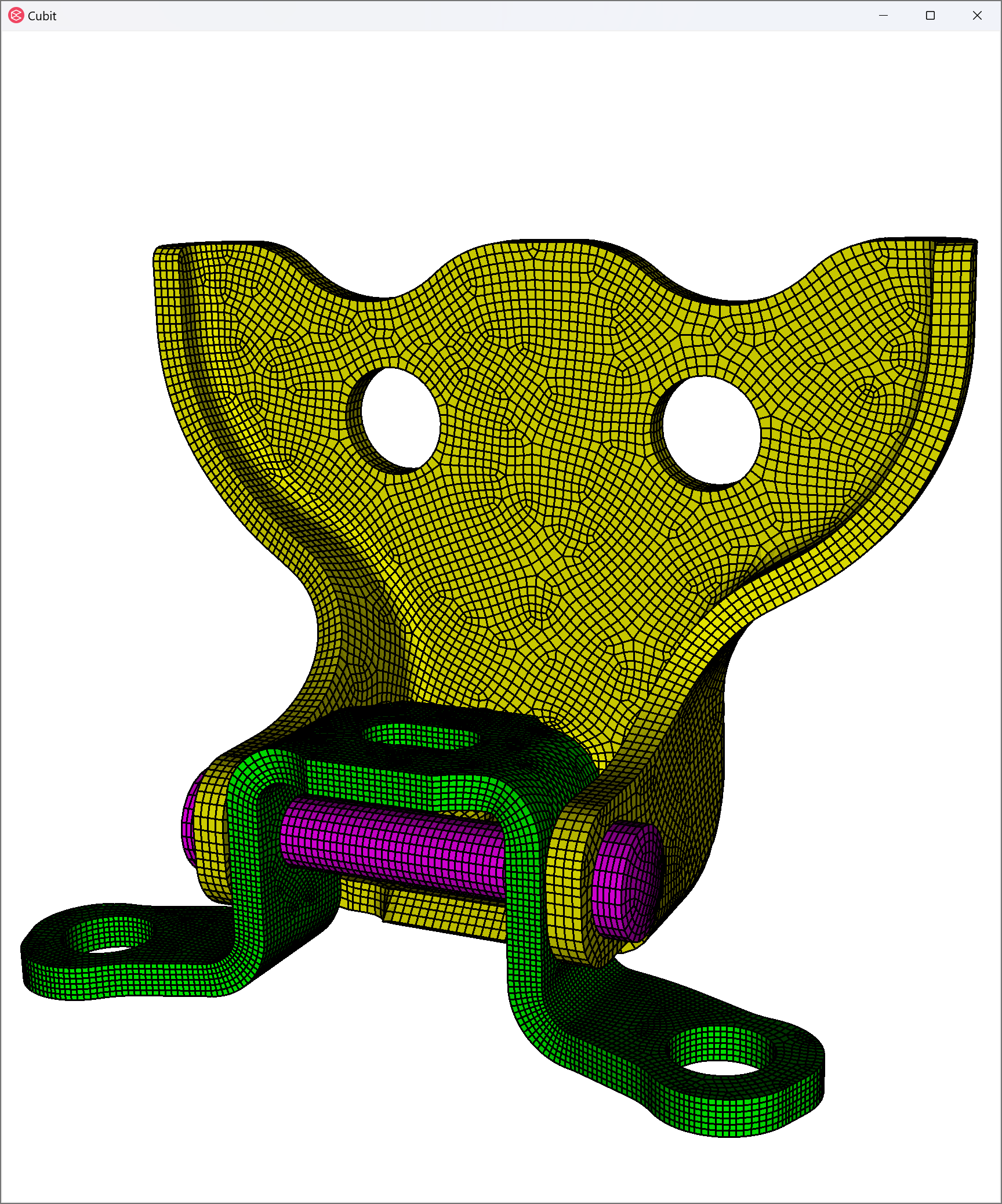
Now we can turn visibility of all the parts back on and view our assembly mesh:
volume all vis on
display
draw block all
Complete journal file
(With some cleanup / slight modifications)
#!cubit
reset
import cubit "Path/To/Door_Lock_Assembly.cub5" nofreesurfaces attributes_on separate_bodies
## ASSIGN BLOCKS
#!python
V = cubit.get_entities( "volume" )
for vid in V:
cubit.cmd( f"block {vid} volume {vid}" )
## BLOCK 1
#!cubit
volume all except in block 1 vis off
composite create surface 3 to 5, 7 to 9, 11, 15, 24 to 27, 32, 33, 44 to 46, 49, 54, 57, 60, 62, 63, 75, 78 keep angle 15
composite create surface 1, 2, 10, 12 to 14, 16, 18 to 20, 22, 30, 31, 36, 39, 41, 47, 48, 52, 53, 55, 61, 64, 66, 68 keep angle 15
composite create surface 40 37 50 58 34 67 77 72 28 23 keep angle 15
composite create surface 51 42 43 56 79 80 74 70 keep angle 15
volume in block 1 size auto factor 2
volume in block 1 redistribute nodes off
volume in block 1 scheme Sweep source surface 209 29 21 target surface 208 sweep transform least squares
volume in block 1 autosmooth target on fixed imprints off smart smooth off
mesh volume in block 1
set smooth tolerance 1e-5
volume in block 1 smooth scheme laplacian free
smooth volume in block 1
set smooth tolerance 0.05
## BLOCK 2
volume all vis on
volume all except in block 2 vis off
composite create surface 81, 85, 91, 95, 100, 102, 105, 110, 113, 114, 118, 130 to 132, 136, 138, 144 to 146, 154, 155, 161 to 163, 165, 167, 168, 171, 172, 175, 180 to 182, 188, 189, 193 keep angle 15
composite create surface 86, 87, 103, 106, 109, 117, 119, 121, 122, 125, 126, 129, 135, 137, 141, 142, 150, 152, 153, 156, 158 to 160, 164, 169, 173, 174, 176, 177, 184 to 187, 190 to 192 keep angle 15
volume in block 2 size auto factor 2
volume in block 2 redistribute nodes off
volume in block 2 scheme Sweep source surface 210 target surface 211 sweep transform least squares
volume in block 2 autosmooth target on fixed imprints off smart smooth off
mesh volume in block 2
set smooth tolerance 1e-5
volume in block 2 smooth scheme laplacian free
smooth volume in block 2
set smooth tolerance 0.05
## BLOCK 3
volume all vis on
volume all except in block 3 vis off
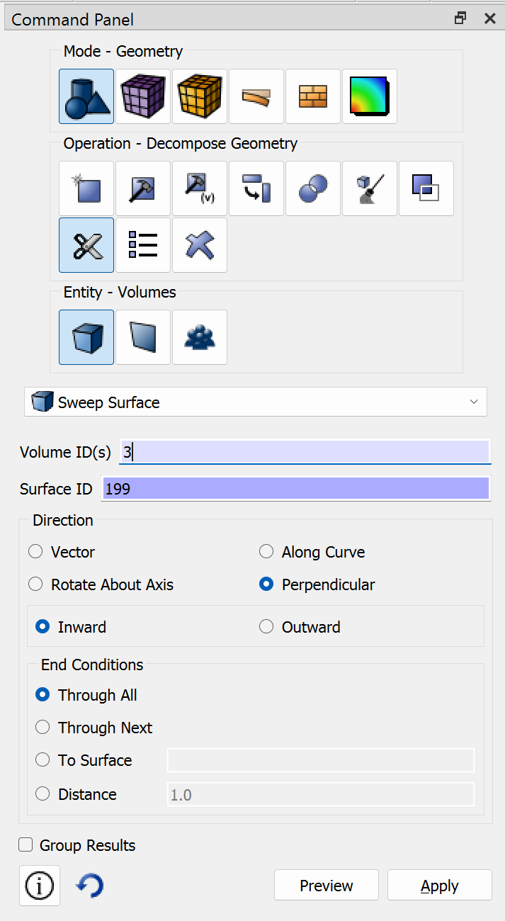
webcut volume in block 3 sweep surface 199 perpendicular inward through_all
webcut volume in block 3 sweep surface 203 perpendicular inward through_all
webcut volume in block 3 with loop curve 487
webcut volume in block 3 with loop curve 488
webcut volume in block 3 with plane normal to curve 490 close_to vertex 304
webcut volume in block 3 with plane normal to curve 608 fraction 0.5 from start
imprint volume in block 3
merge volume in block 3
volume in block 3 size auto factor 5
volume in block 3 scheme auto
volume 21 3 6 13 16 11 8 18 scheme polyhedron
mesh volume 21 3 6 13 16 11 8 18
mesh vol in block 3
vol all vis on
display
draw block all