Hi everyone,
If you are running into cases where fillets, sliver faces, or small CAD details are forcing very small surface elements (and a lot of manual prep), an angle-based selection + compositing workflow can help simplify the geometry without losing important boundaries.
Workflow (high level):
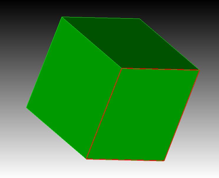
- Select faces by dihedral angle to group faces that are smoothly connected, while preserving true feature lines.
- Start with a tight max-angle (for example ~1°) so you do not accidentally merge across sharp edges.
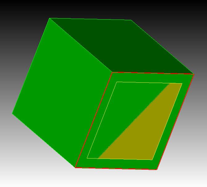
- Consider keeping a few anchor surfaces (remove a few faces from the selection before compositing) so the mesher still has clean boundaries, vertices, and usable start curves.
- Mesh coarse first, then evaluate. For many solid-mechanics workflows, higher-order tets can represent curvature well without forcing excessive refinement everywhere.
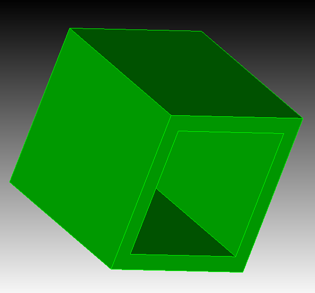
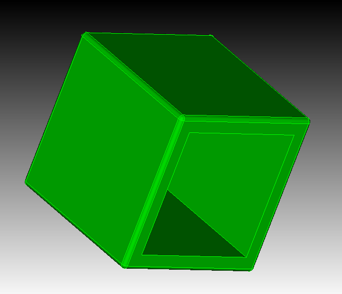
- Validate the result by inspecting geometry representation and element quality after meshing.
Why this helps:
You can often reduce surface count and eliminate problematic tiny faces, while still preserving the boundaries that matter for analysis.
If anyone has a favorite max-angle range for typical CAD fillets (or examples where this approach did not behave well), We would be interested to hear what you have seen.
Here are some scripts and models you can use to test this workflow:
reset
bri x 1
bri x 0.8 y 0.8 z 0.9
move vol 2 z 0.05
subtract vol 2 from vol 1
modify curve 4 1 2 3 5 6 7 8 9 10 11 12 blend radius 0.025
reset
bri x 1
bri x 0.8 y 0.8 z 0.9
move vol 2 z 0.05
subtract vol 2 from vol 1
modify curve all blend radius 0.025
gasket.sat (332.6 KB)
BiW-Arm-Bracket-C_120207.stp (319.3 KB)
332211_qif_bracket_revh_gjv.sat (1.1 MB)