
On a recent flight I thought I’d have some fun and mesh a model inspired by an r/FEA post, and I made use of a few useful commands that I thought I’d share.
Creating the geometry
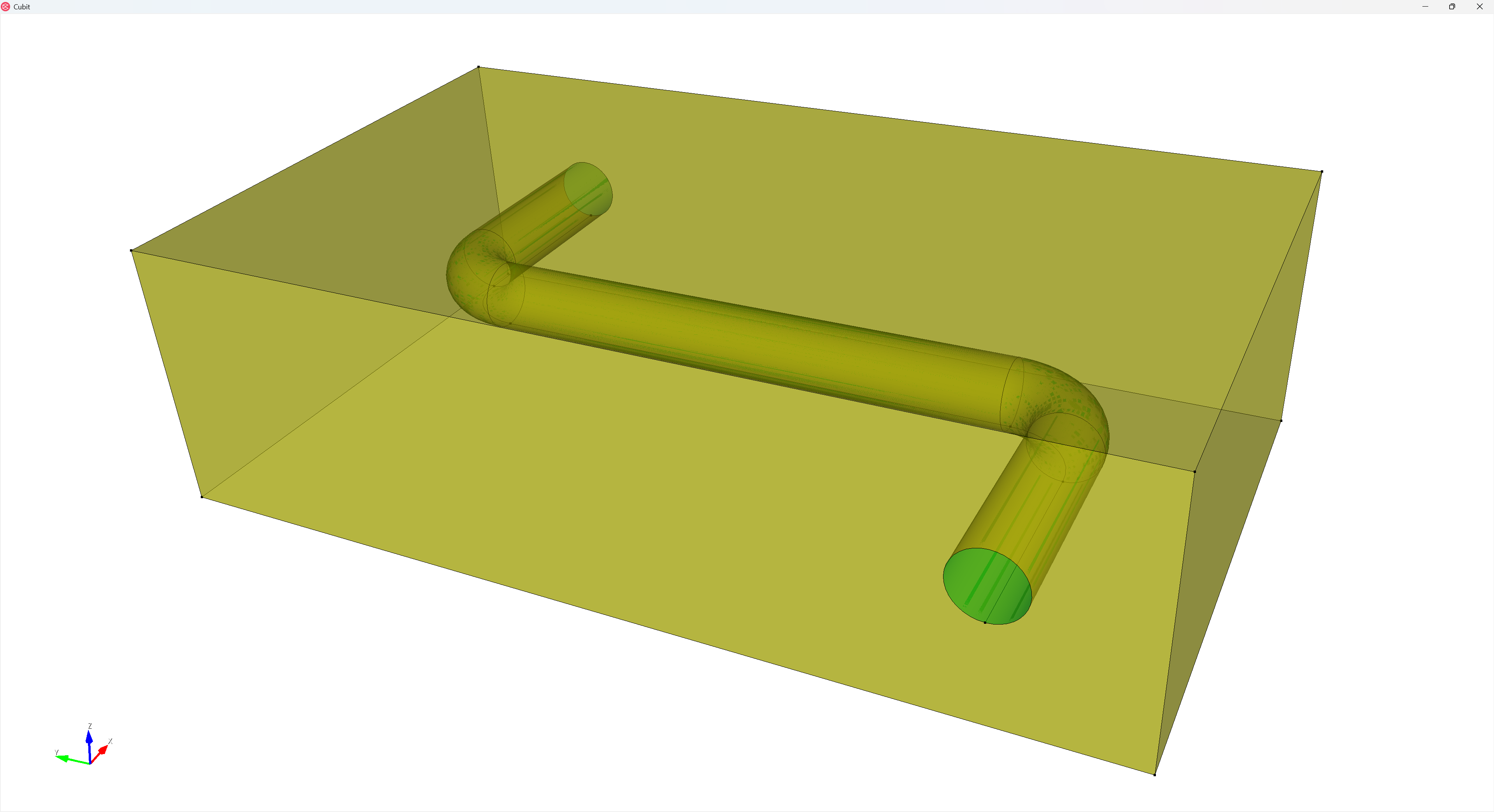
Here’s a snippet that generates a representative geometry:
reset

## Create Geometry
create curve location 0 0 0 location 0.75 0 0
create curve arc radius 0.25 center location 0.75 0.25 0 normal 0 0 1 start angle 270 stop angle 360
create curve location 1 .25 0 location 1 2.25 0
create curve arc radius 0.25 center location 1.25 2.25 0 normal 0 0 1 start angle 90 stop angle 180
create curve location 1.25 2.5 0 location 2 2.5 0

create surface circle radius 0.125 xplane
sweep surface 1 along curve 1 2 3 4 5
delete curve 1 2 3 4 5
compress

brick x 2 y 3.5 z 1
move Volume 1 location 0 0 0 include_merged
remove overlap volume 1 2 modify volume 2
Assigning sets
I usually like to assign my sets prior to decomposing my geometry for meshing.
## Sets
block 1 vol 1
block 2 vol 2
#... etc
Partition for meshing
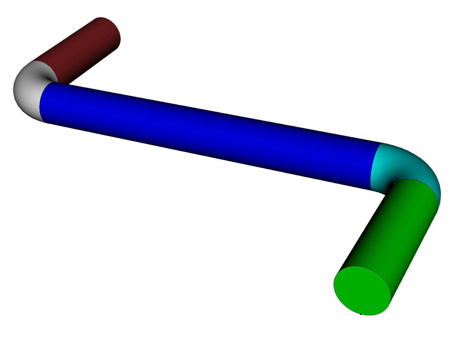
First I decompose the pipe into segments using the circular loops along its length:
## Partion for Meshing
### Pipe
webcut volume in block 1 with loop curve 10
webcut volume in block 1 with loop curve 8
webcut volume in block 1 with loop curve 6
webcut volume in block 1 with loop curve 4
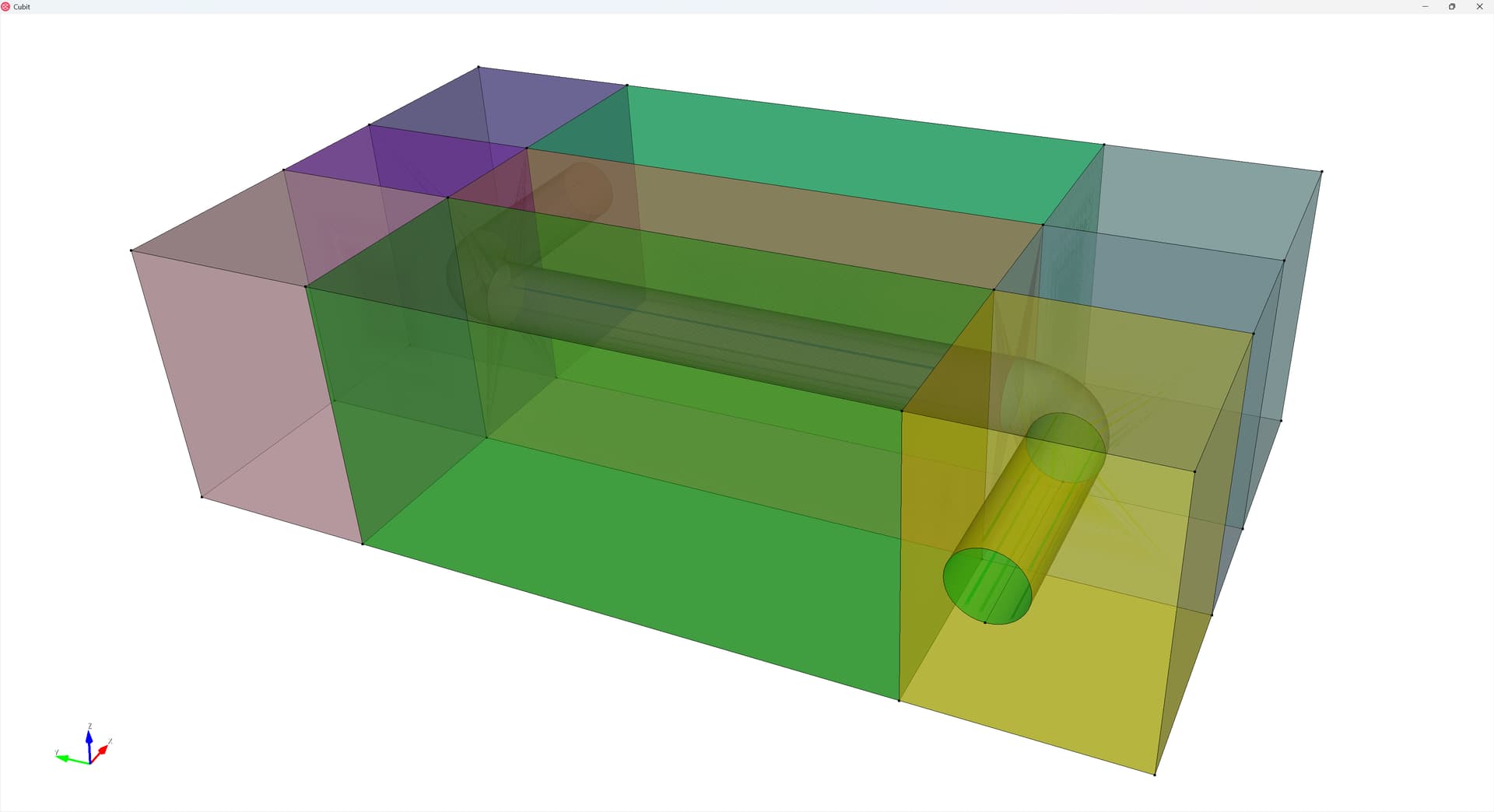
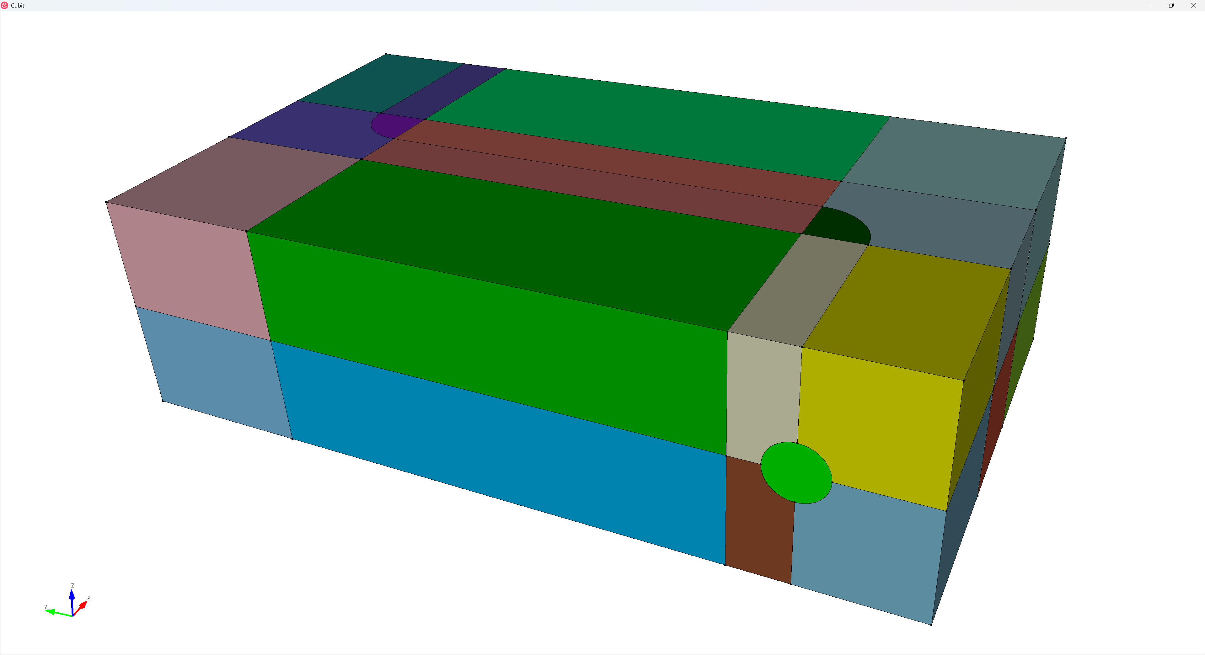
Those webcuts give me planes that I can then use to cut the soil (yellow / block 2) geometry:
webcut volume in block 2 with plane from surface 28
webcut volume in block 2 with plane from surface 30
webcut volume in block 2 with plane from surface 33
webcut volume in block 2 with plane from surface 34
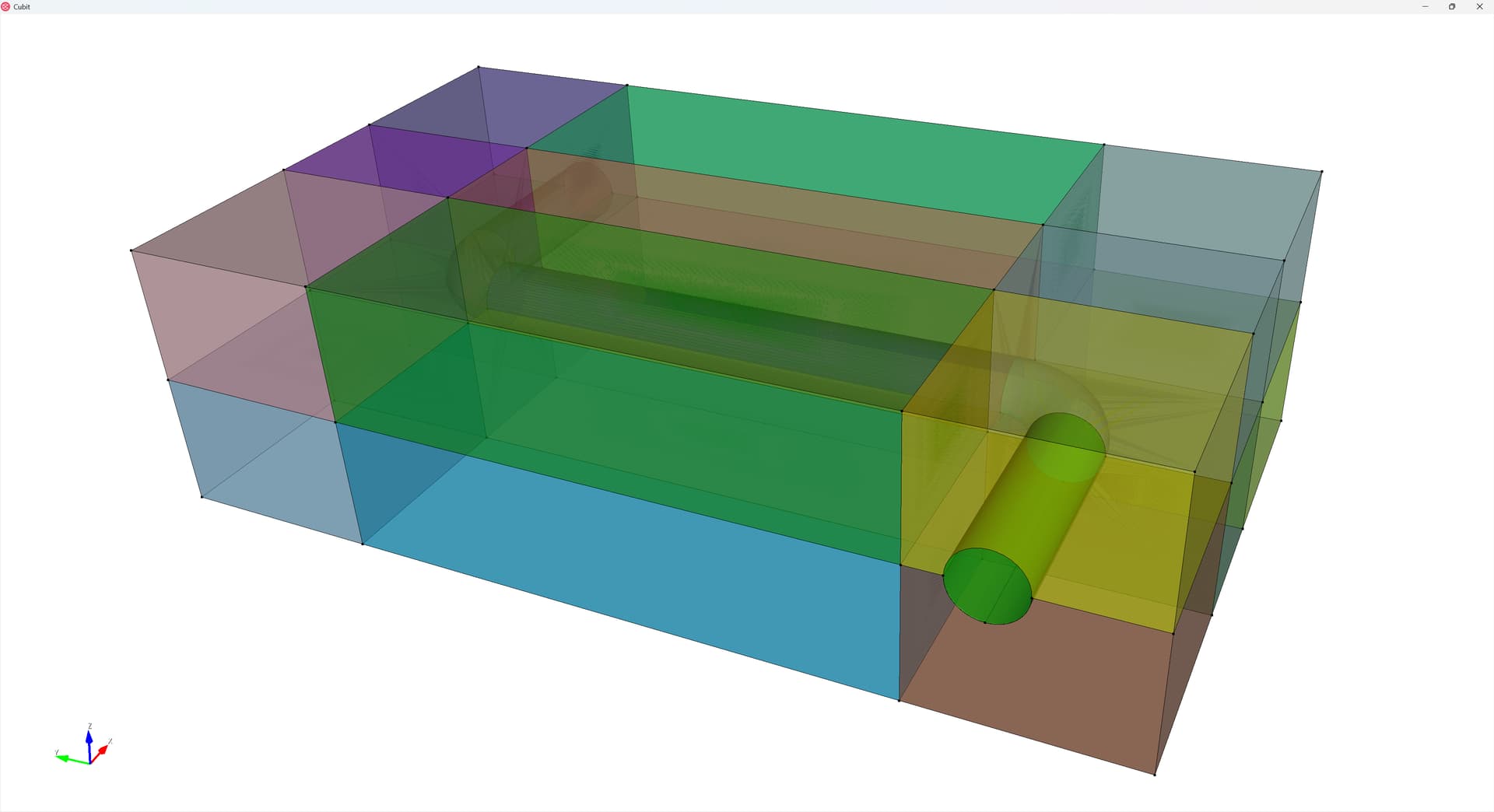
Then I cut the soil in half along the z-direction:
webcut volume in block 2 with plane zplane offset 0
And finally I sweep the curve from the pipe along the z-direction in both directions to produce cuts. Here I got “lucky” that the geometry generated the curve in the center of the cross-section (as projected in the z-direction) - but there are ways I could generate equivalent curves if they hadn’t.
webcut volume in block 2 sweep curve 7 11 9 5 3  vector 0 0 -1 through_all
webcut volume in block 2 sweep curve 7 11 9 5 3  vector 0 0 1 through_all
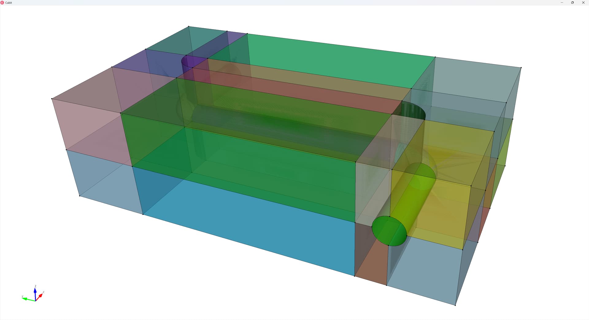
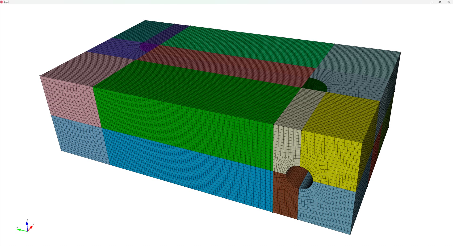
So here’s my fully-webcut geometry:
Ensure mesh continuity
To enforce a contiguous mesh, I imprint and merge the geometry:
## Ensure Contiguous Mesh
imprint all
merge all
Generate the mesh
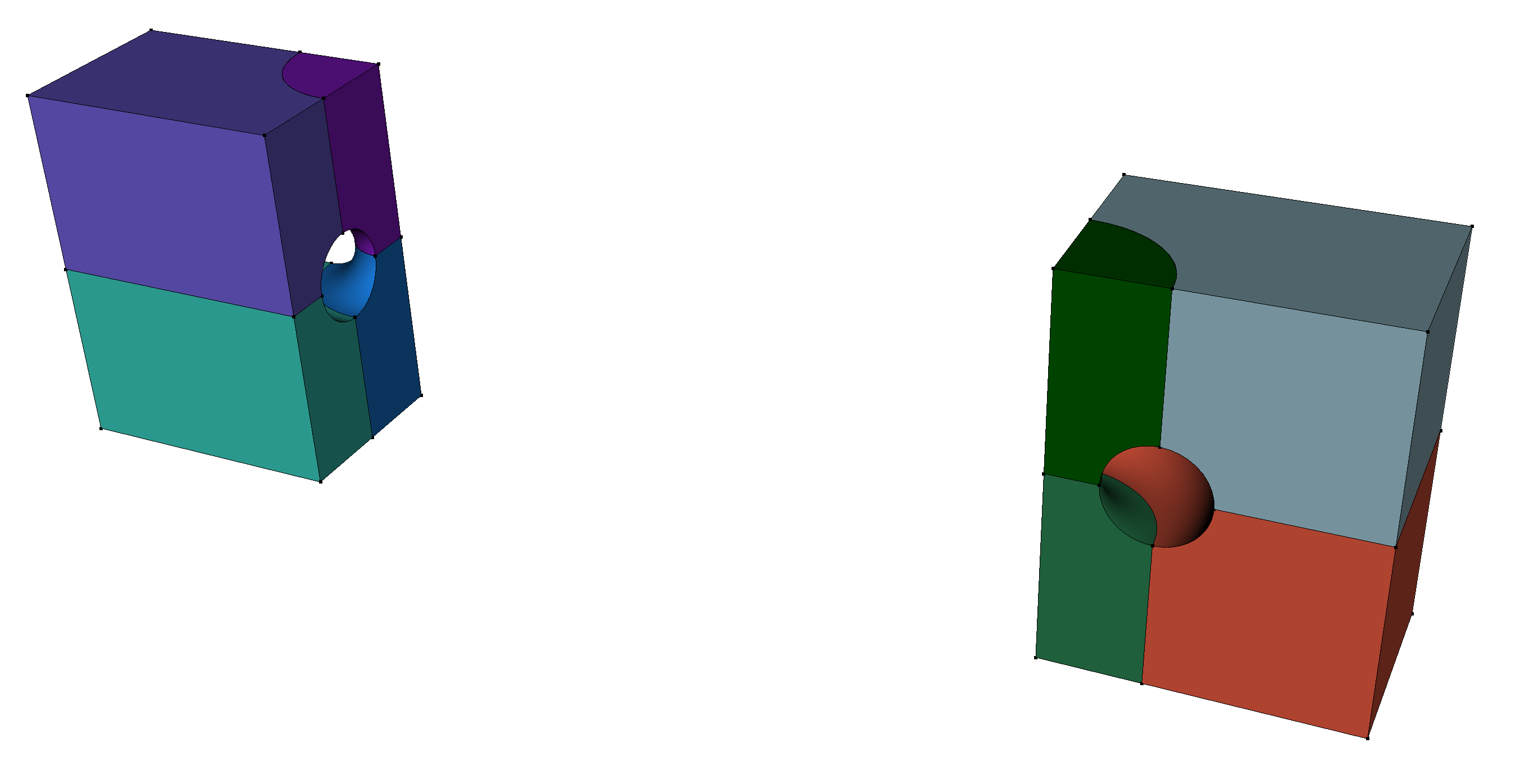
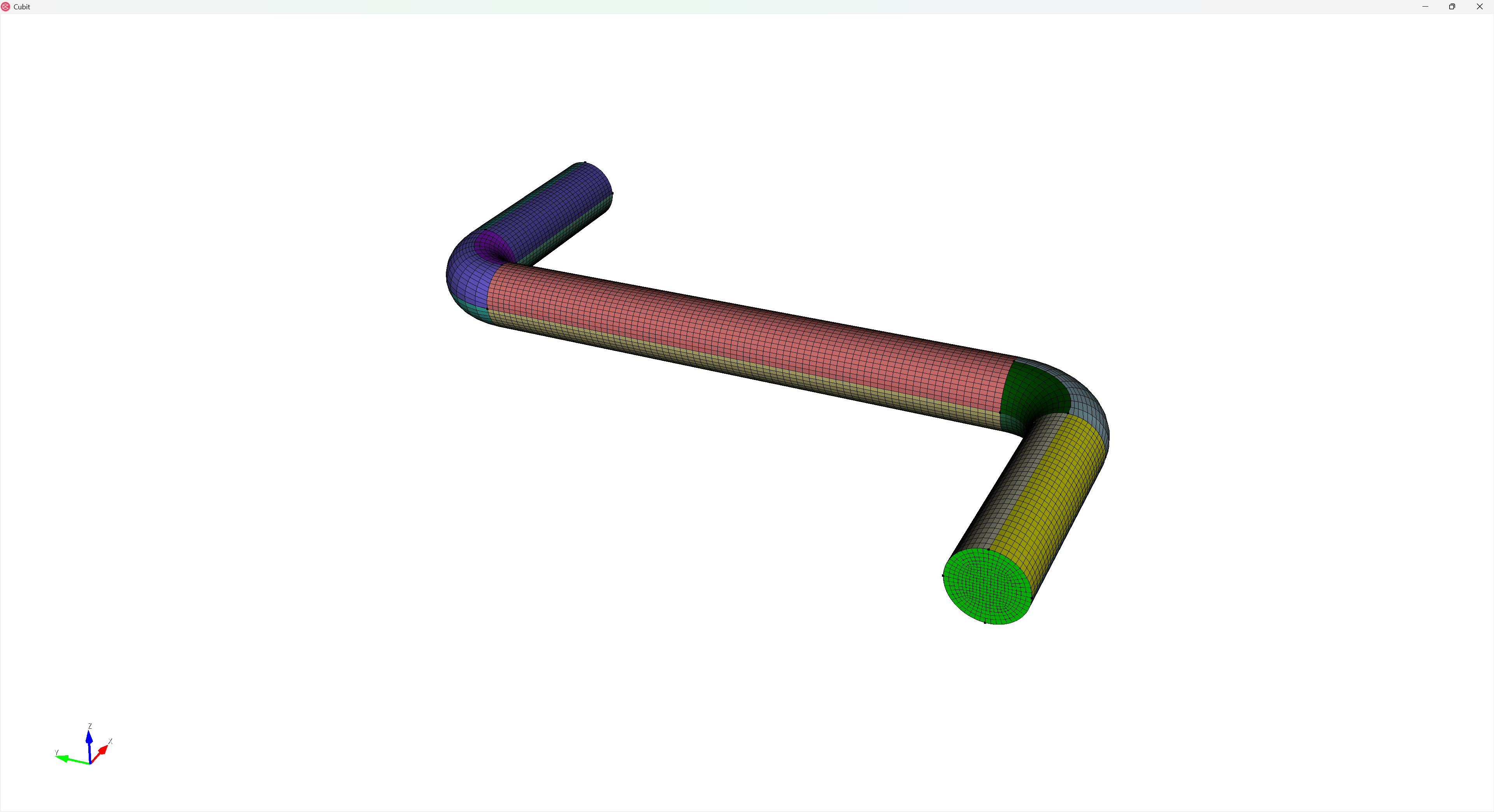
Now I want to generate the mesh. First, I recognize that the soil regions around the pipe elbows will need the polyhedron mesh scheme:
And I also want the pipe cross-section to use the circle mesh scheme. However, I found the the circle mesh scheme needed to have an even number of edges around its circumference and each “quadrant” will need the same number of edges to be compatible with these polyhedron-scheme volumes. There are two useful commands that will let us enforce these constraints: curve <ids> Interval {Even | Odd} and curve <ids> Interval same.
I begin by setting my (global) element size, assigning the circle surface mesh scheme, and applying these constraints:
## Mesh
reset vol all
#{mesh_size=0.025}
volume all size {mesh_size}
surface 7 1 28 34 scheme circle
Curve 328 529 394 511 329 395 504 522 238 286 472 488 237 285 479 495 206 207 455 457 210 209 464 466 interval even
Curve 328 529 394 511 329 395 504 522 238 286 472 488 237 285 479 495 206 207 455 457 210 209 464 466 interval same
Then I assign the polyhedron mesh schemes and mesh these volumes. Note that because the polyhedron mesh scheme requires all surfaces to have the polyhedron surface mesh scheme assigned, I assign the polyhedron scheme to the volumes that join the elbow sections shown above as well:
Then I mesh the rest of the volumes in the soil block, which automatically assigns schemes to the remaining volumes in the block:
mesh vol in block 2
I then assign sweep schemes to the pipe volumes and mesh them from one end to the other:
volume 1 4 5 6 7 redistribute nodes off
volume 1 4 5 6 7 autosmooth target on  fixed imprints off  smart smooth off
volume 7 scheme Sweep  source surface 1    target surface 34   sweep transform least squares
volume 6 scheme Sweep  source surface 34    target surface 32   sweep transform least squares
volume 5 scheme Sweep  source surface 32    target surface 30   sweep transform least squares
volume 4 scheme Sweep  source surface 30    target surface 28   sweep transform least squares
volume 1 scheme Sweep  source surface 28    target surface 7   sweep transform least squares

mesh volume 7 6 5 4 1
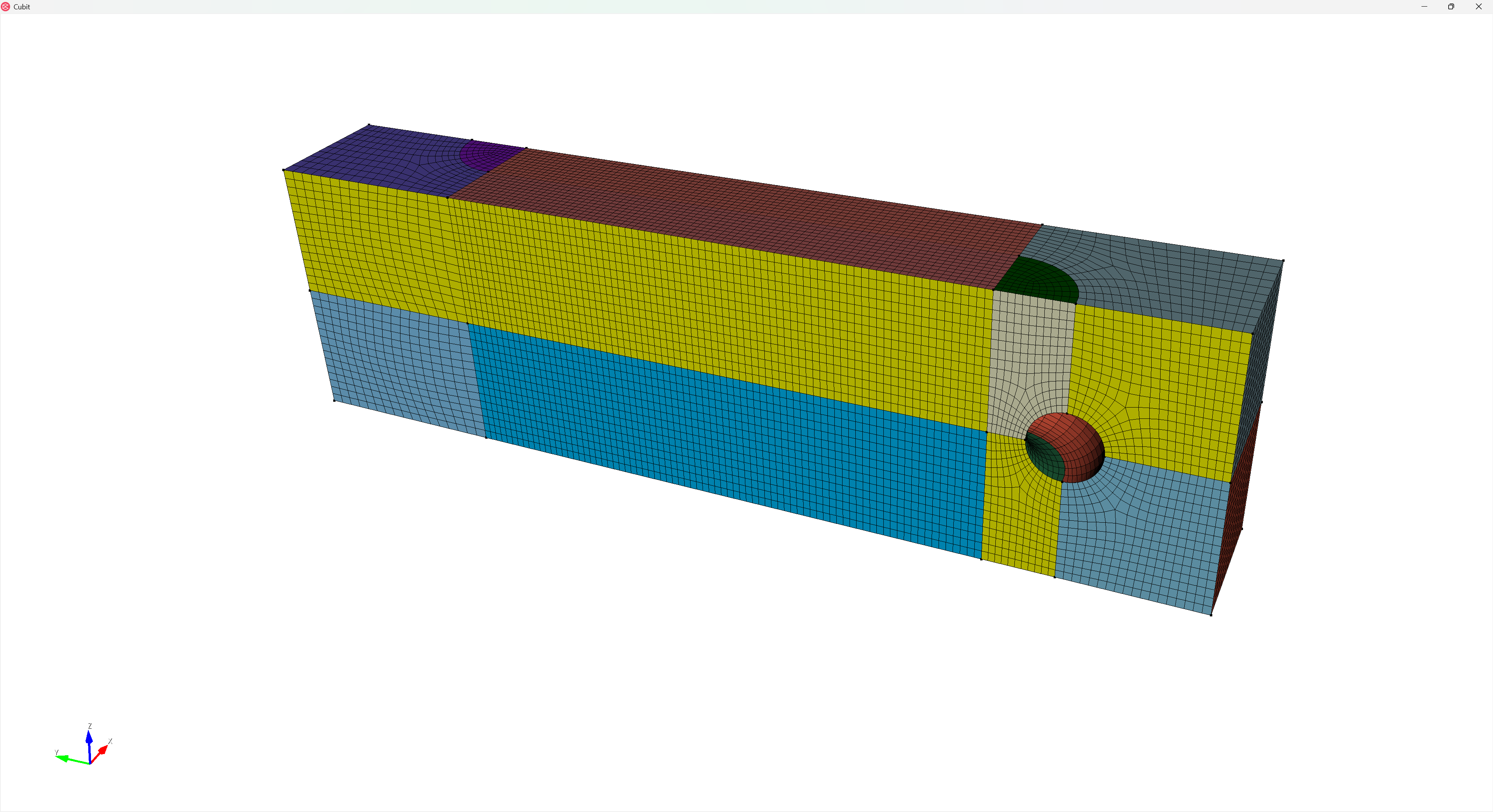
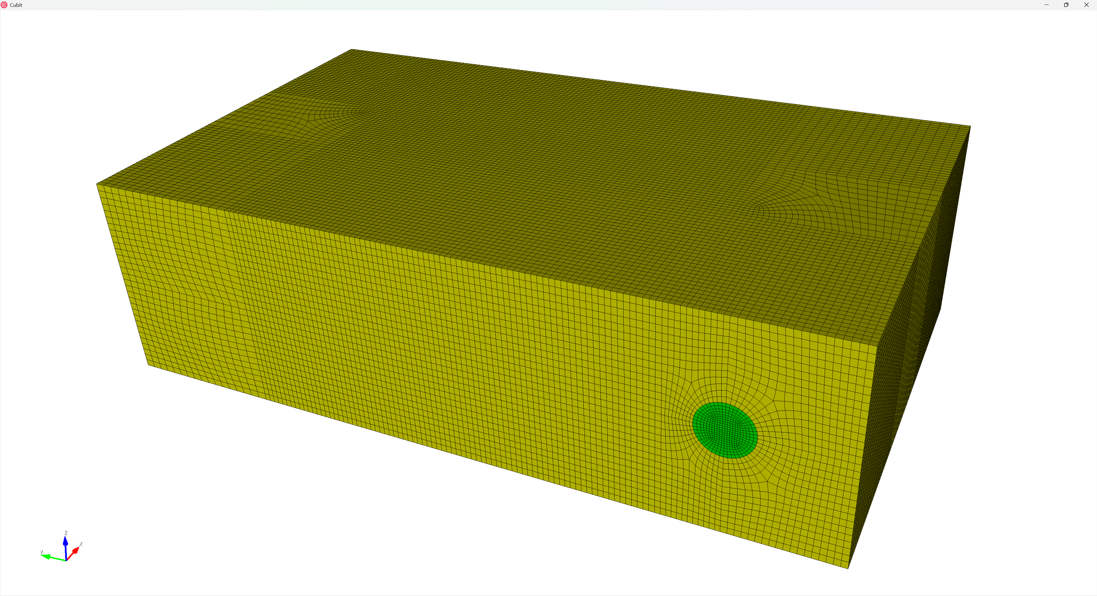
Drawing the meshed volumes, colored by their block assignments yields:
And we can draw the mesh quality (I like scaled Jacobian):
quality volume all scaled jacobian global draw mesh
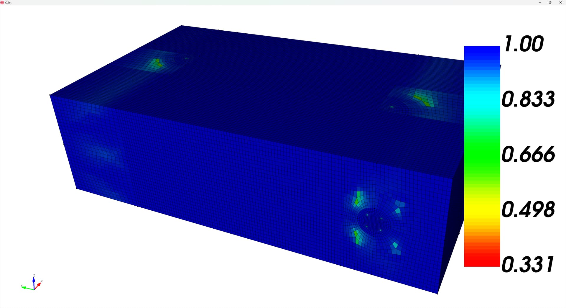
A “worst” element of 0.331 isn’t bad, but let’s apply some smoothing to see if it improves. I recommend smoothing to improve the condition number:
volume all smooth scheme condition number beta 2.0 cpu 0.5
smooth volume all
And redrawing the mesh quality the mesh appears a fair-bit better:
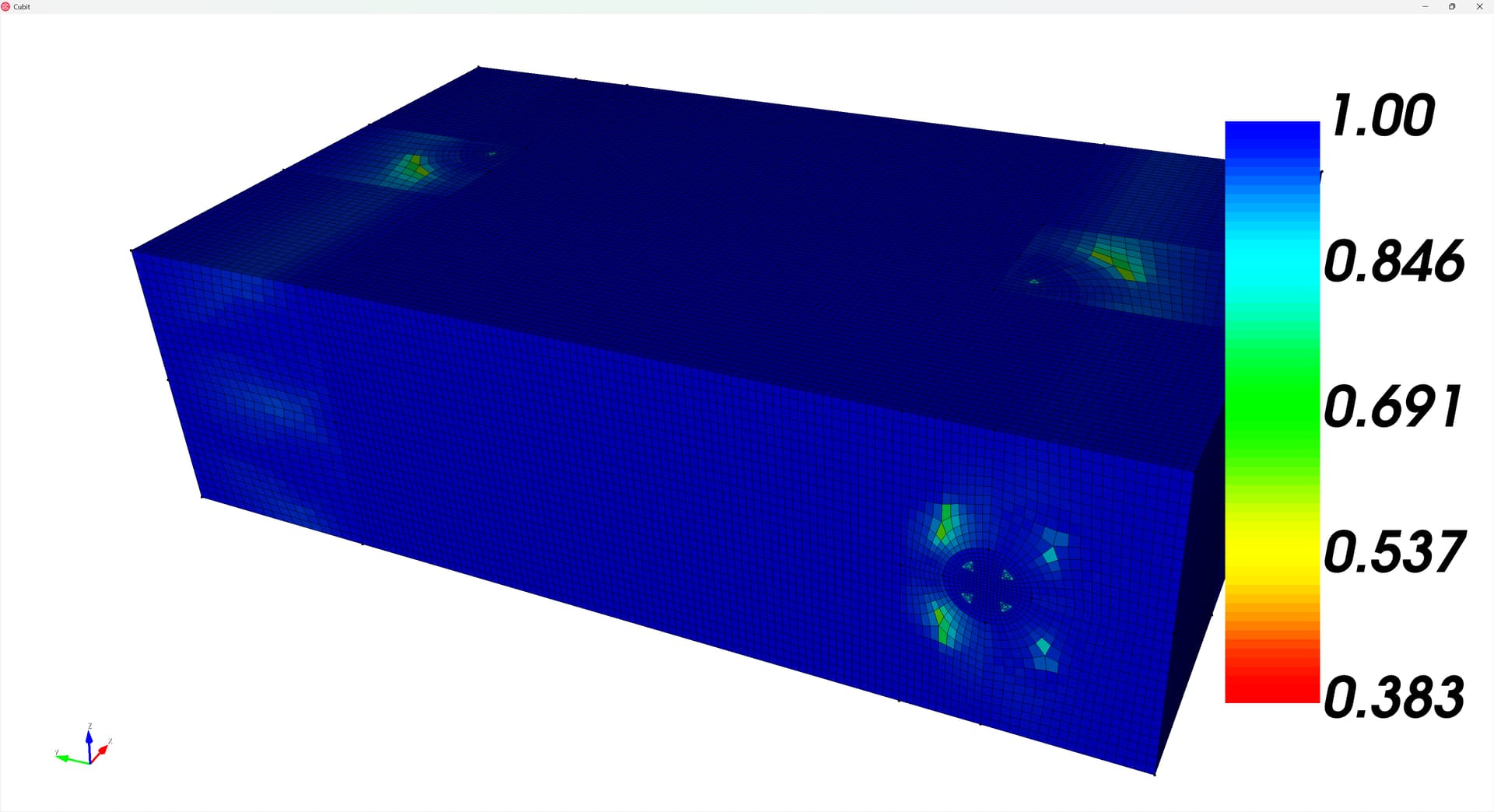
Happy meshing!