711-testing.jou (20.7 KB)
Hello!
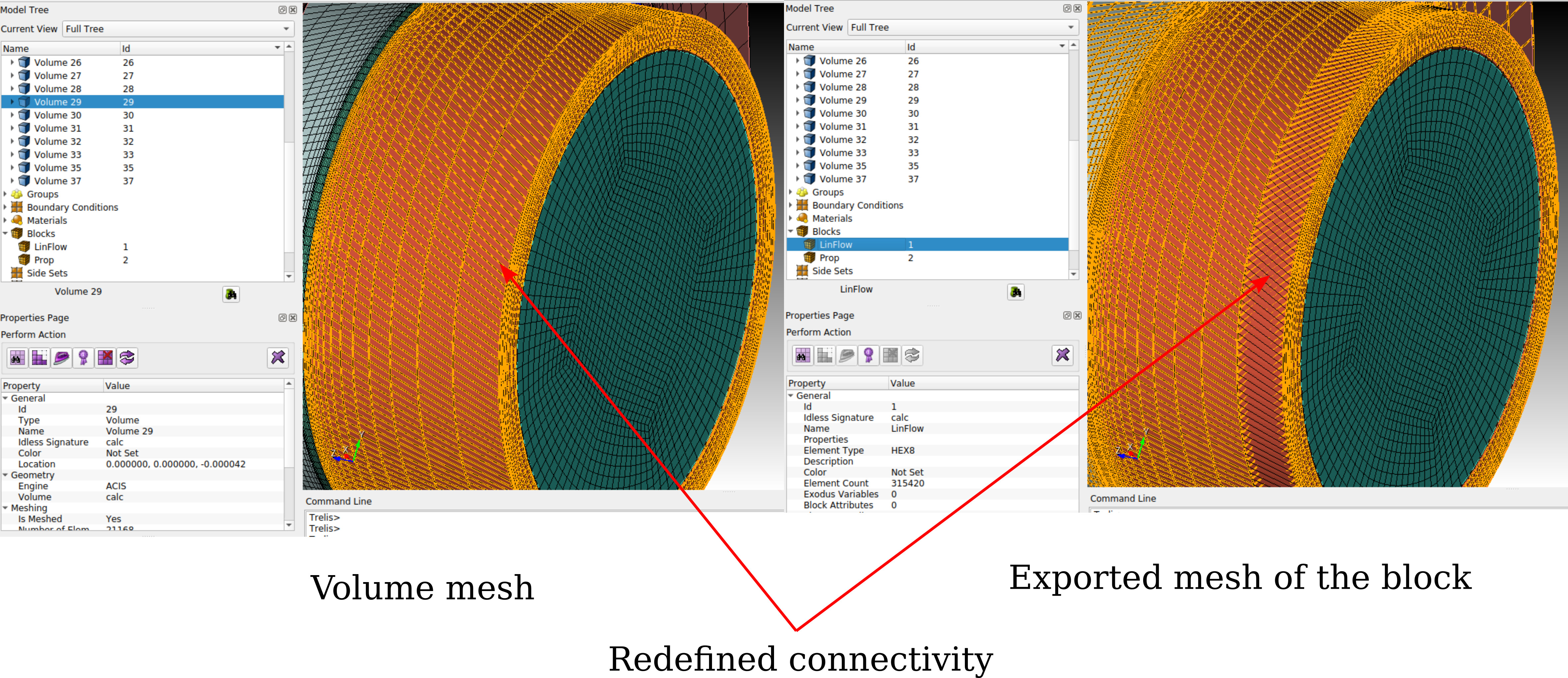
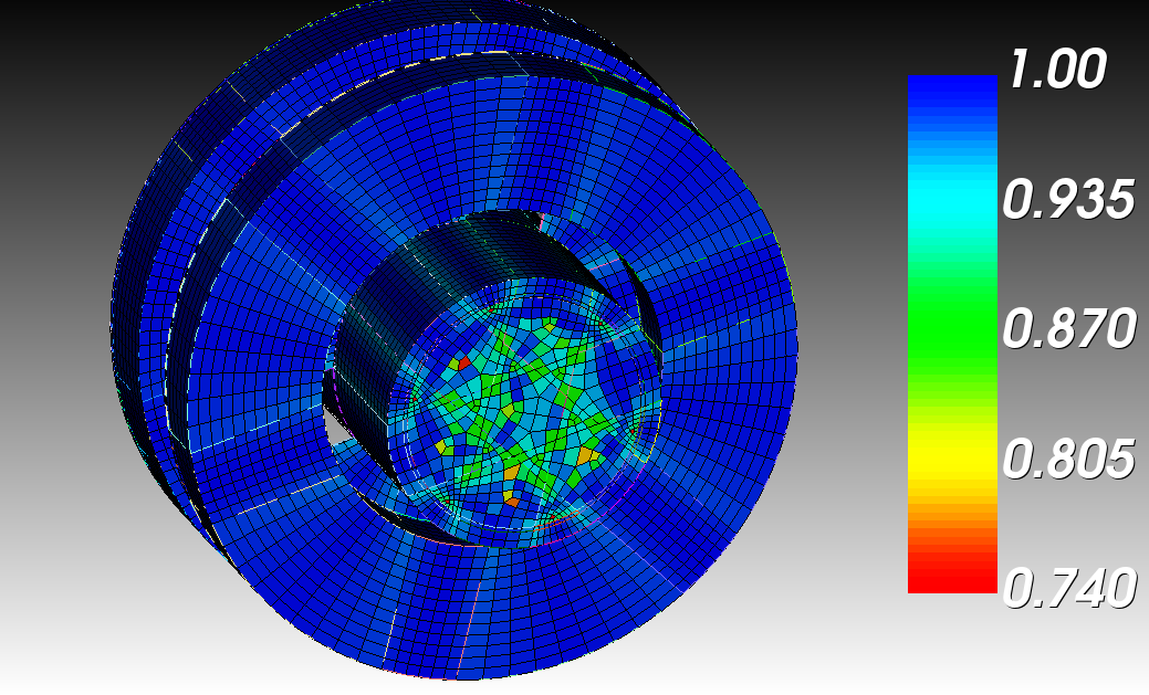
I have prepared the geometry and mesh for an acoustic coupler but have problems defining blocks. During the meshing process, everything is working fine, and the mesh seems to be nice and regular. When I continue and define a block containing certain volumes, the mesh within the block (and therefore the exported .cdb file) changes. In the uploaded file this is the case for volumes 29, 30, and 31. It is only one row that somehow gets its connectivity redefined and somewhat shifted/twisted, but for conforming meshes this is not usable anymore. The strange thing is that taking a look at one shared boundary, the mesh can behave differently in the adjacent blocks depending on the volume containing the original mesh. Hence, I end up with a mesh that was conform during the meshing stage, but is non-conforming in the end since one side (block) changes the connectivity and the other one does not. I tested this for an inherently non-conforming mesh as well as for a conforming mesh, which led to the same problem.
I also tested this on multiple operating systems and versions of Trelis/Cubit - all with the same result. Is there a workaround for this bug?
Hi Mr. Mayrhofer,
i am currently not sure what you want to achieve.
Do you mean the element connectivity gets changed on defining the blocks?
Or do you want to achieve a mesh where the blocks have a conforming mesh but coincidence/overlapping nodes at their interface?
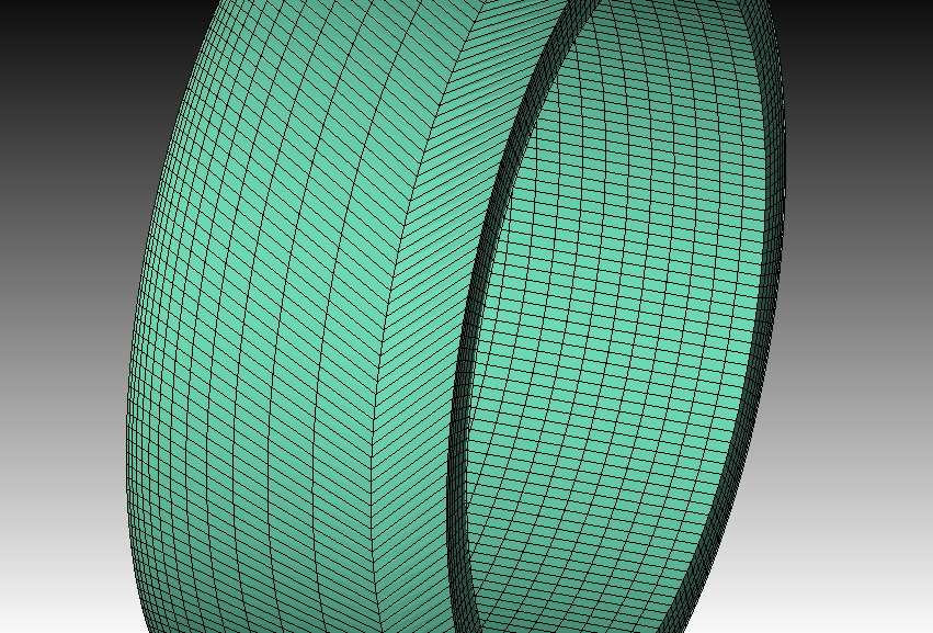
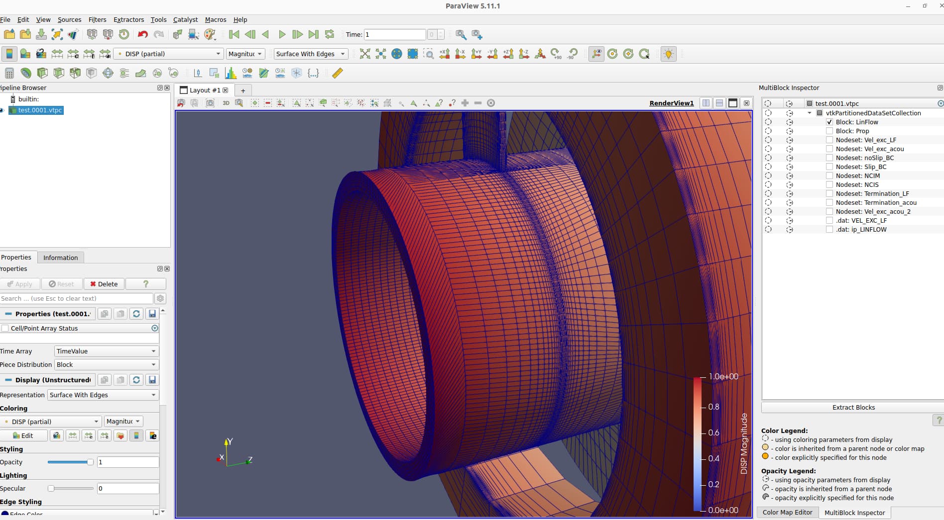
Currently you don’t have coincidence nodes or a conforming mesh at the interface between the blocks.
thank you for the fast reply! Sorry for not being clear about my problem.
My problem is that the mesh changes when I add the already meshed volumes to a block. In this case, volumes 29, 30, and 31 are affected. One row of elements of the mentioned blocks differs when inspecting it directly on the volume or within the according block. Since the mesh data of the blocks is also used for the export, this is not just a visualization problem.
You are completely correct. The script I provided uses a non-conforming mesh. I have a second version that uses a conforming mesh at the very interface you show in your screenshot. What I wanted to emphasize is that the problem persists for both versions and is not ideal for the already non-conforming version. The conforming version, though, is not usable anymore due to the bug. The reason for this is that the mesh (connectivity) changes on only one side of the mesh, introducing a “non-conforming interface” albeit sharing the surface at this very interface.
I just tried it and yes, I can confirm this behavior. The same also holds true for the other two volumes.
I just want to note that volume 29 exhibits this behavior, but is not as problematic as volume 30, where this also happens when a merged volume is adjacent. The adjacent volume (volume 20 in this case) does not flip the last row, resulting in a non-conforming mesh.
Would it help you if I upload the journal file for the conforming version as well?
Thanks for the other version. I found out whats going on.
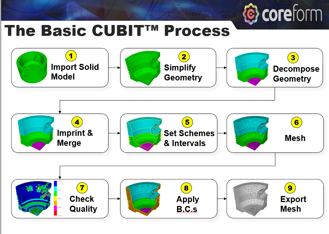
To put it simply. you are leaving the basic cubit workflow when you are meshing before merging.
Looking at volume 30. It is meshed before it gets merged with volume 20. So the mesh is already set for volume 30 and it seems when meshing volume 20 only the intervals on the curves are checked, but not the actual connectivity of the faces for the merged surface. That’s probably the reason why cubit doesn’t throw an error on situations like this. Adding the volume to a block doesn’t actually change the connectivity. You can try that out with draw hex all in vol 30 before and after adding volume 30 to a block.
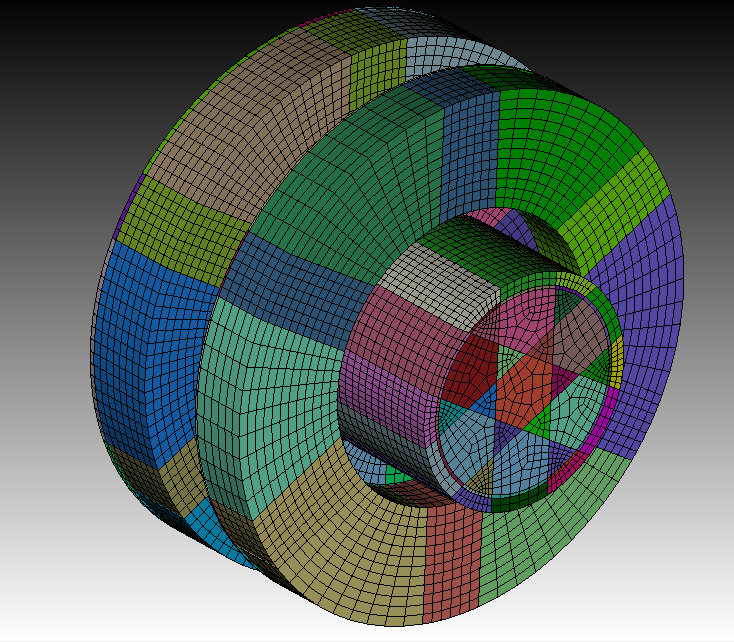
Doing a quick and easy decompostion after the geometry is created, will create a lot of volumes,
but those can be imprinted, merged and meshed with no real effort.
Thank you for the input!
I know that I left the standard route - I did since I just wanted to test if I get a working mesh by “quickly” merging the lower part afterward (rather quick and dirty version, to be honest). Nevertheless, this does not explain why this is the case for both versions. In the non-conforming version I have the same problem and there I followed the standard procedure.
Regarding regularizing: That is true, unfortunately, I was forced to do so
since Cubit randomly cut edges of volumes during merging. This resulted in edges that were cut in such a way that the desired meshing scheme was not usable anymore. I assume the regularization is then to be blamed for both cases. Do you know why this happens and how to avoid that without a complete domain decomposition? The sizing functions I use are crucial for the simulation since viscous effects are at play.
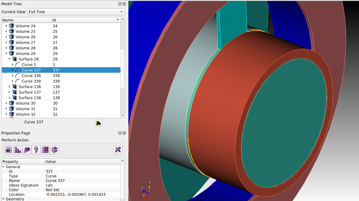
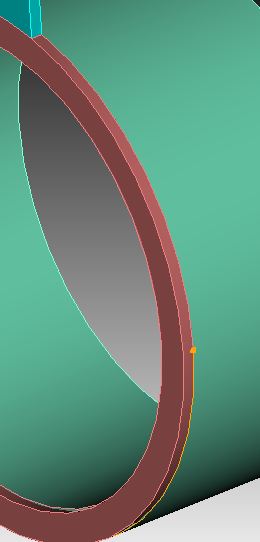
I have attached a screenshot of one of the curves that are randomly split (curve 337). I have no idea, why this cut happens to begin with, but that is where I had to intervene to get a usable mesh.
I looked again at your nonconform version. Although the rows gets an offset, the elements are still connected and its still a conforming mesh. I can run a simulation with calculix without a problem.
But i the element row shouldn’t get an offset to begin with. We will look into this behaviour.
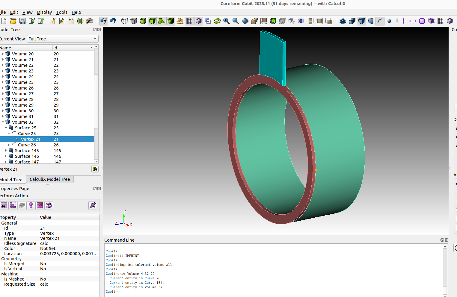
It is not a randomly cut from cubit. That’s what happens when you do a imprint command. Cubit wants to get the same topology for adjacent entitities.
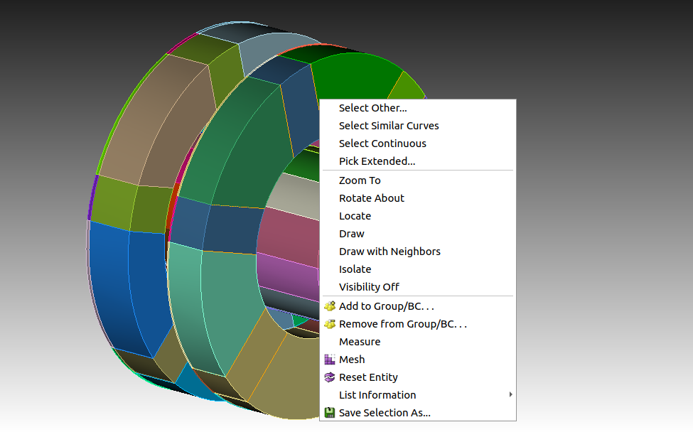
When you take a look at volume 4 29 32. The vertex for the arc curve is highlighted. Thats a fix point for the topology. Also the vertices of the edges from volume 4 are fix points. So when we do an imprint cubit will preserve these and try to imprint this topology on the adjacent entities.
I looked again at your nonconform version. Although the rows gets an offset, the elements are still connected and its still a conforming mesh. I can run a simulation with calculix without a problem.
Yes, the non-conforming version does work, you are entirely correct. Due to the distorted elements the quality of the result will suffer a bit, but that’s it.
But i the element row shouldn’t get an offset to begin with. We will look into this behaviour.
Thank you very much! Although I did leave the standard way of meshing (also with the whole regularize/imprint story) I still think that this offset shouldn’t occur in the first place. Hence, I thought why this is the reason for my problems.
It is not a randomly cut from cubit. That’s what happens when you do a imprint command. Cubit wants to get the same topology for adjacent entitities.
When you take a look at volume 4 29 32. The vertex for the arc curve is highlighted. Thats a fix point for the topology. Also the vertices of the edges from volume 4 are fix points. So when we do an imprint cubit will preserve these and try to imprint this topology on the adjacent entities.
Thank you for pointing that out, I completely missed the vertex! Sorry for assuming some randomness, it just seemed a bit random to me, since (if I remember correctly) not all volumes were affected by the cut. But I guess this is due to the algorithm as well as the initial position of the vertices corresponding to the circular surfaces.
You can still use the sizing after the merge. With the select similar feature it should not be to troublesome.
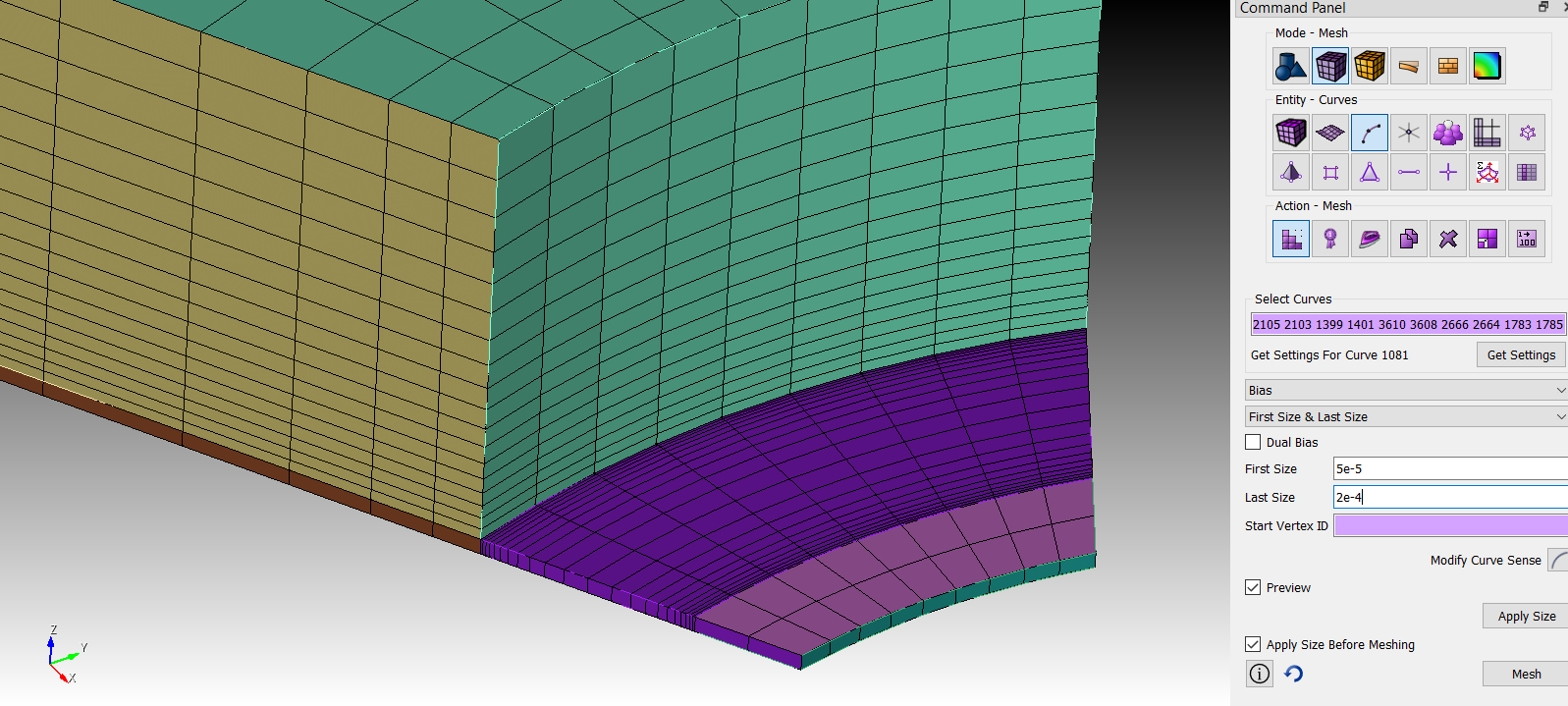
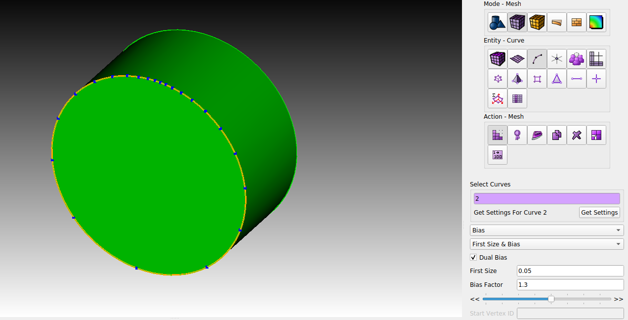
You mean the sizing function in radial direction, right? Because I also wanted to have a dual bias sizing function around the outer contour (the circular part) so that the elements are small at the entrance to the outer ring but gradually grow the further away they are from the connecting region. I did not find a way to treat multiple curves as one for the bias sizing function, did I miss something or was the version I used too old?
Thank you for your reply, from what I’ve seen you are using the same commands / options as I do usually. What I meant is an option to treat two curves (which have been separated) as one for the bias scheme. If this is not possible, I have to define the bias for each curve separately since I need to increase the starting size for each section.
See the attached example: If I want to get the mesh shown in “bias_desired_distribution” with a body that is somehow split (for example due to the imprinting command as it happened in the example above), I have to define each curve individually.
What I wanted to know is if there is some option to treat all selected curves as one in order to apply for example a dual bias to the whole set of curves. If I do this now, each curve gets its own dual bias, since each curve is treated individually - see “bias_actual_distribution”.
Of course, treating all curves as one includes some cuts which need to be considered by the algorithm and it will also result in only an approximation of the sizing function, but it would be very convenient in my opinion. I hope this makes my point more clear.
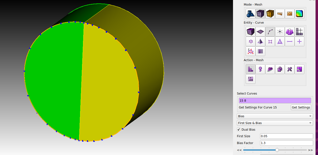
You can treat two merged curves more or less as one. But not all selected curves. For treating two curves as “one”, you will have to use the start vertex option. But that will only work for curves with the same start vertex. It is not propagating further. Doing a dual bias, ends up just like you’ve written.
What happens in this short example is simply a bias scheme for two curves with a given start vertex.
This produces comparable results like the dualbias scheme in your image ‘bias_desired_distribution’.
reset
create cylinder h 2 r 4
webcut volume all xplane
#webcut volume all yplane
imprint vol all
merge vol all

curve 7 14  scheme bias fine size 0.2 factor 1.1 start vertex 5
mesh curve 7 14
Exactly, in this simple example you can fall back to two bias schemes. If multiple curves are involved, I have to start at each curve separately with a new “first size” to have a more or less propagated bias over multiple curves.
Hence, I have to deal with this separately or maybe cut the geometry differently to save some time.