
Does the Matching Tetrahedral Meshes functionality (command is: Meshmatch tet sideset <id_list> onto sideset ) allow matching meshes on two bodies when the interface separating them is exactly overlapping? The documentation says, “A single target sideset and one or more source sidesets should be provided. The source sideset should be completely enclosed in the target sideset so that the boundaries of the two sidesets do not intersect.” For example, I have two cubes side by side touching one side. Cubes are of the same size. So the sides of the cubes that are touching effectively are co-located and their boundary curves are also co-located. Can I match the meshes of these two cubes on that common side?
Hi,
This case works where one cube is smaller.
reset
bri x 1
bri x .5
vol 2 move x 1

vol 1 2 scheme tetmesh
vol 1 2 size .1
mesh vol 1 2
sideset 1 surf 6
sideset 2 surf 10
block 1 vol 1
block 2 vol 2
disass mesh vol 1 2
del vol 1 2

meshmatch tet sideset 2 onto sideset 1
Sideset 1 and 2 are exactly aligned after mesh matching.
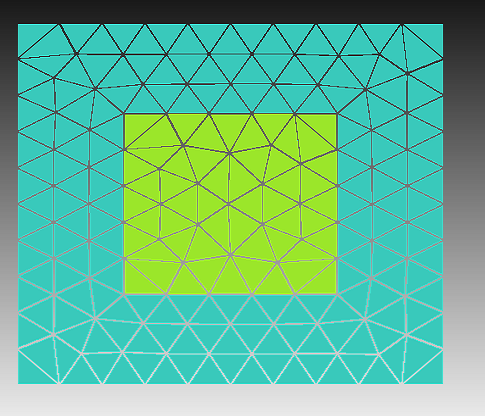
Reading the docs, it seems to indicate that the boundary curves cannot overlap. Making both cubes size 1, aligning them properly and repeating the process above, fails. It seems that the boundary edges cannot overlap.
Karl
1 Like
Thank you @karl. Is there a minimum distance between the two sets of boundary curves/edges that define they are overlapped? Or is there a tolerance that is used to check if boundary edges/curves are overlapped in this case?
The documentation doesn’t list anything. I would guess that you want enough room to create a well-formed tetrahedron. I would guess it should be at least half the element edge length.
Karl
I noticed that the documentation does not mention any tolerance. Can you please ask the developer if they can provide a definitive answer?
The original developer is no longer on the Cubit team. Reading some code, it looks like the buffer distance is 20% of the larger edge length in the two mesh-matched samples. This code was written as part of someone’s dissertation. It just gets the first edge of the first triangle in the list and uses 20% of that edge length.
If you were to get the average edge length reported from
quality edge all length
and use 25% of that value, you are probably OK.
However, in practice, it does not appear that this is a hard tolerance. The meshmatch will succeed if you can create valid triangles on the surface. Note that the element quality will be awful.
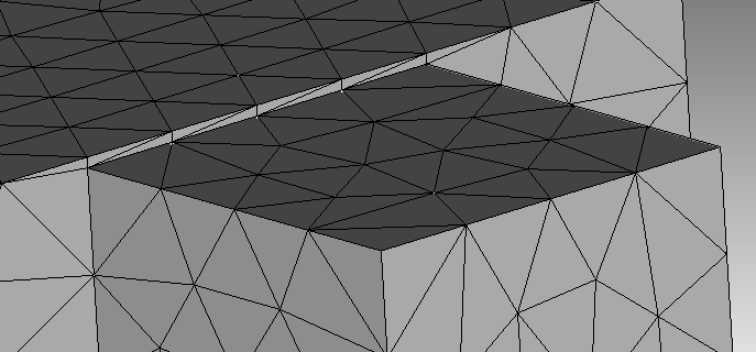
See the example below,
Karl
reset
brick x 1
brick x .4
vol 2 move x .7

vol 1 2 scheme tetmesh
mesh vol all
block 1 vol 1
block 2 vol 2
vol 2 move y .295
sideset 1 surf 6
sideset 2 surf 10
disassociate mesh vol all
del vol 1 2
meshmatch tet sideset 2 onto sideset 1
“…the buffer distance is 20% of the larger edge length in the two mesh-matched samples.” and “…the first edge of the first triangle in the list and uses 20% of that edge length.” Will the first edge of the first triangle in the list be the largest edge? “However, in practice, it does not appear that this is a hard tolerance.” What do you mean by the a hard tolerance?
What I’m saying is that testing shows that I can get much closer to the edge than 20% of the edge length. I took the journal file above and changed the value of the y displacement in the linevol 2 move y .295 until the meshmatch failed. You can get really close to .3, but at some point, the area of the triangle face on the surface approaches zero and meshmatching fails.
Karl