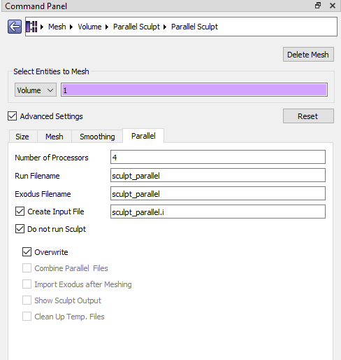
I love how easy it is to create a mesh of an irregular volume with “Parallel Sculpt”.
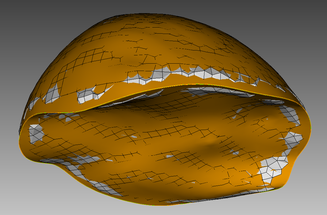
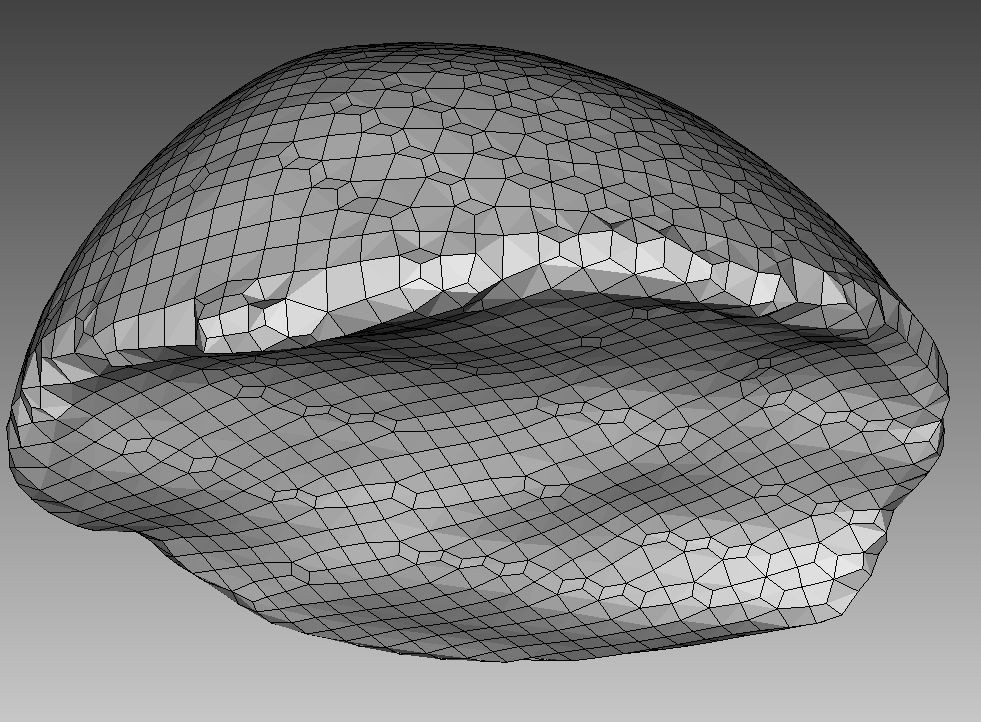
However, when I create a mesh with sculpt all edges are smoothed and rounded. See this screenshot with the volume (with sharp edge) and the resulting mesh with rounded edges:
There is a beta-capability, that is not exposed in the GUI so you’ll need to use a terminal (command prompt on Windows) to access it. The command-line parameter is --capture and it accepts a value that specifies which features to capture. Below is a print-out of the manual for the capture functionality:
Input file command:   capture <arg>
Command line options: -c <arg>
Argument Type:        integer (0, 1, 2)
Input arguments: off (0)
                 on (1)
                 external_surfaces (2)
                 projections_only (3)
                 feature_angle_smooth (4)
                 topology_smooth (5)
Command Description:
    This is an experimental option still in development. Nodes at the surfaces
    of a default sculpt mesh will not necessarily exactly lie on the geometric surfaces
    prescribed by the input STL geometry.  While this characteristic can provide
    additional flexibility for defeaturing and element quality, there are cases where
    a more exact surface representation may be desired.  The capture option attempts
    to address this by extracting sharp features and/or projecting nodes to the facet
    geometry.

    Several options are currently being studied as possible solutions. They include
    the following:
      0 = (off) Capture option is off.  No attempt is made at capturing sharp features.

      1 = (on) STL geometry is used as basis for feature capture.  A user defined
    feature angle is used (capture_angle) to first generate groups of facets from the
    STL geometry based on capture_angle.  Topological curves are defined based
    on projections to closest surface facets and edges. With default smoothing option,
    the surface nodes will be projected to the closest STL surfaces as a final step
    before exporting the exodus mesh.  Consider using smooth = to_geometry option.

      2 = (exterior_surfaces) Only exterior surfaces are captured.  Uses the same
    procedure as described in capture = 1, except that interior surfaces (those with
    two adjacent volumes), will be ignored in the capture and projections stage.

      3 = (projections_only) For this option, additional topology based on feature
    angle is not extracted.  Only the final projection of surface nodes to the STL
    facets is done.  Note that this option is useful for organic shapes that do not
    have sharp features, or where sharp features should be ignored.

      4 = (feature_angle_smooth) This option uses the procedure outlined in
    capture = 1, except that the smooth = to_geometry is used by default.
    Note that capture = 1 used with smooth = to_geometry should be
    identical to this option.

      5 = (topology_smooth) Curve topology is defined similar to capture = 1,
    except that element face topology is first determined based on closest assigned
    facet.  Curve topology is then extracted based on adjacent element face associativity.
    Surface node projections are only done for nodes that have unambiguous neighbor
    associativity. This provides for a tolerant approach to resolving topology that
    may result in defeaturing.  (i.e. where the STL facet topology may be locally
    more complex than can be resolved by the prescribed resolution).  This option
    also uses the smooth = to_geometry option as default for smoothing.  Also
    note that capture = 5 it is only currently available for serial execution
    (j=1)