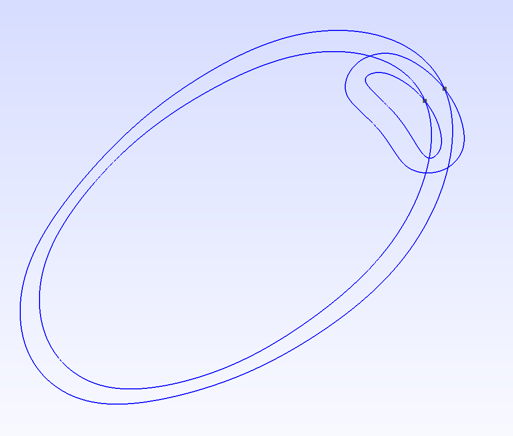
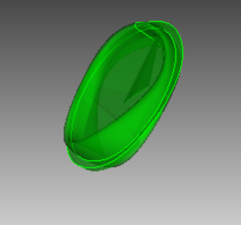
I’m having a strange issue where when I import a step file into Cubit, one of the surfaces is unrecognizably wrong. I’ve tried with autoheal on, and with autoheal off. This has happened to me with several (albeit, similar) files, all of which have worked properly in the other uses I’ve had for them. I’ve attached an image of how the step files is meant to behave, and one of what happens in Cubit.
I’m really at a loss as to how to how to troubleshoot this, so any advice would really be appreciated! If it’s useful, I can also attach the file.
Thank you,
Eleanor
I’m not sure why the extra surface gets created. However, we can clean it up pretty easily. You can go into surface select mode, select the spurious surface, right click and select “Remove” at the bottom of the menu.
Thank you for looking into this! Unfortunately, this approach won’t quite work because the issue (at least, on my device) is not an extra surface getting created, but one of the surfaces being incorrect. I expect two very similar, concentric surfaces from this model, and instead I get one correct one, and then the very wonky one.
For my current uses, I don’t need to hex mesh or webcut this geometry, though I appreciate your offer to look into that.
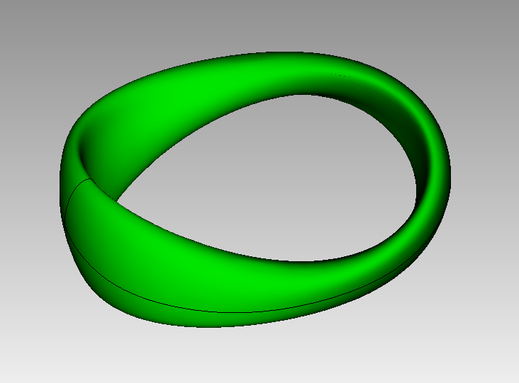
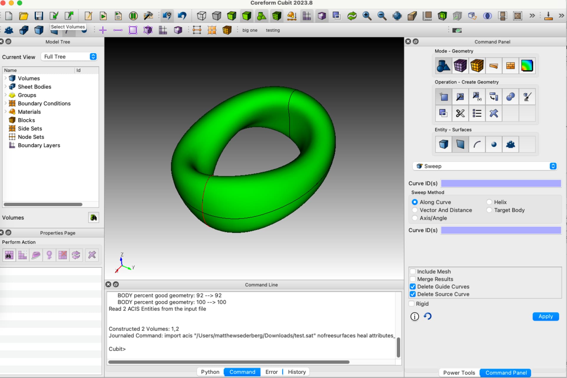
Eleanor, I just tried importing your file into Rhino3d, then exporting a .sat file. This .sat file seems to open just fine in Cubit. Does this look good on your end? test.sat (1.9 MB)
What is the result that you want? This process creates two sheet bodies (surfaces) in Cubit. The outer sheet body is not closed. The curves on the XY plane of the outer shell are duplicated. Do you want two volumes? Maybe one volume enclosed by the inner surface and the outer volume occupying the space between the two shells? What is your target analysis with this model?
As far as I can tell, the above picture looks correct; I expected to get two very similar surfaces, and one volume between them. The outer surface not being closed is a bit concerning—I’ll download Rhino3d and see if this works on my end, or if that’ll cause issues. Thank you so much for trying things to figure this out!
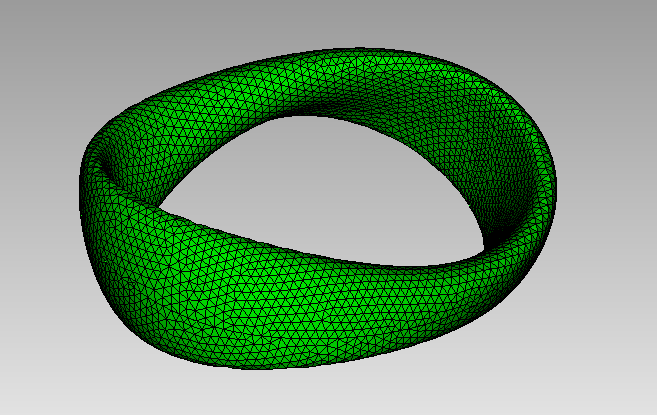
Yep, I tried, and while it looked good on the outside, you were right about some of the issues. I’m looking for one volume enclosed by the inner surface and outer volume, occupying the space between the two shells. Alas.
One thought, is it possible to crack the volume into halves or quarters in the CAD modeler before exporting it? Breaking up those complex surfaces might help with the translation.