Dear users and developers,
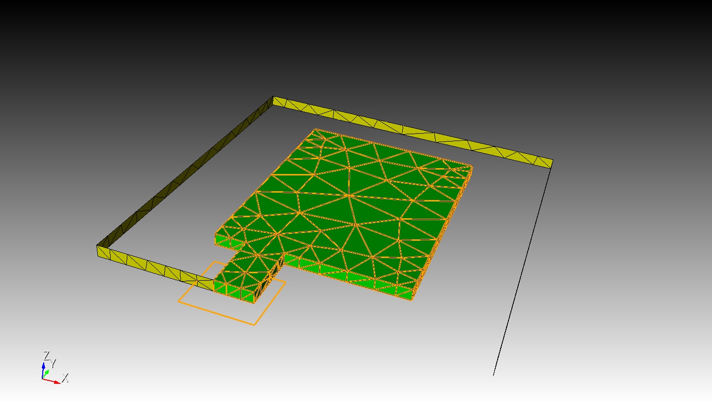
I am trying to use cubit to generate a 3D mesh. I need to use the tetrahedral edges overlapping with the orange loop (curves) in the figure. Therefore I need to export this information.
This loop can be imprinted to the volumes correctly. Then I tried the following commands,
(1) merged volume all
(2) mesh volume all
(3) Sideset curve 130 131 132 133 134 135 136 137
Finally it was exported as .bdf file.
I can not find the information related to Sideset curve in the .bdf file.
Did I miss someting? The .cub5 file was also uploaded.
Thanks,
cubit01.cub5 (762.8 KB)
Hi @neilForum,
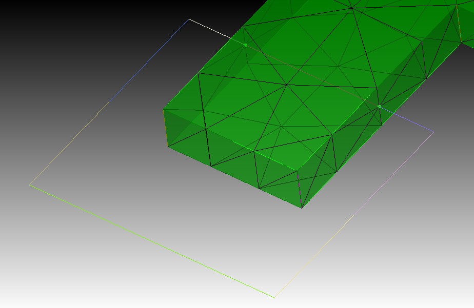
the curve that you are trying to export are only imprinted at the boundary intersection of the volumes. This means that only vertices were imprinted and there is no curve in the volume that will be respected when you mesh. Also the curves are not meshed so there are no elements that could be exported in the sideset.
I would recommend that you decompose the volumes with webcuts to obtain edges that overlap with your curves. This will also give you more control for meshing.
Also the whole geometry looks like it could be hex meshed with a little bit of decomposing.
Thanks a lot. Norbert. Very helpful information. Webcut can make it.
I have another question. When multiple web cuts are made, a volume can be divided into several subvolumes. If the geometry contains two or three volumes with different materials, it becomes challenging to differentiate the subvolumes from Volume 1 and Volume 2 after the cuts. The same issue applies to surfaces.
Do you have a straightforward command that can assist with this? For instance, if Volume 1 is cut into two subvolumes, can these subvolumes be grouped together automatically instead of manually
Thanks,
Xiaodong
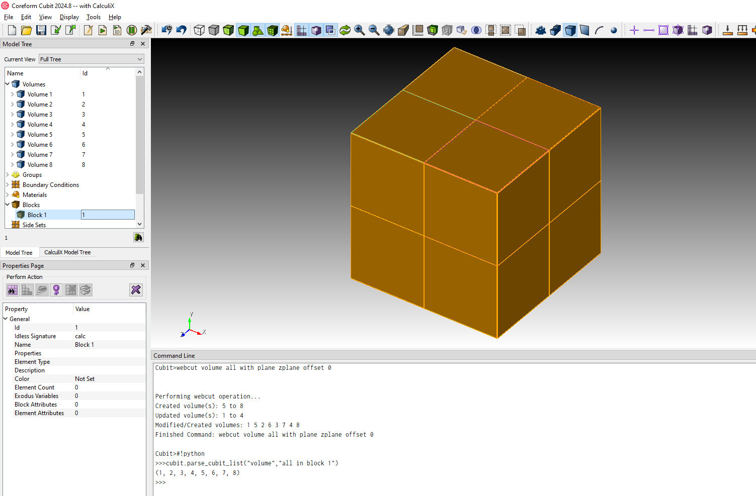
If the volume is already assigned to a block before doing the webcuts, then the subvolumes should be added to the block too.
#!cubit
reset
create brick x 1
block 1 add volume 1
webcut volume all with plane xplane offset 0
webcut volume all with plane yplane offset 0
webcut volume all with plane zplane offset 0
Thanks a lot. Very helpful.
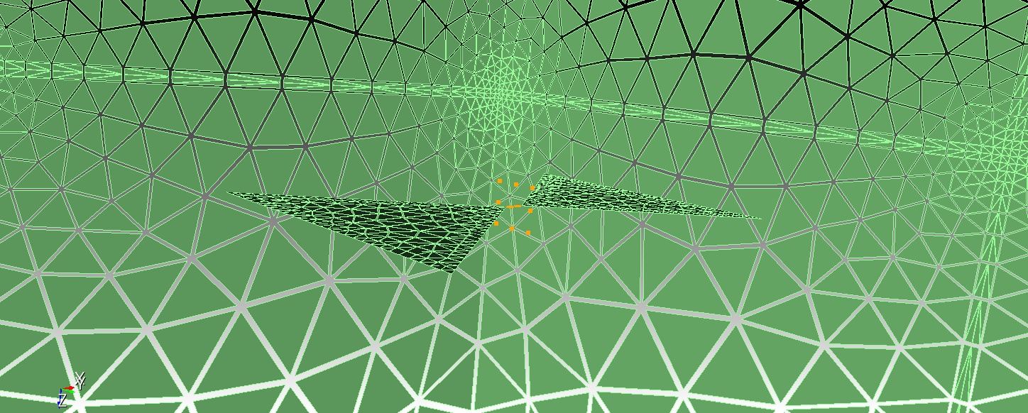
Hi, Norbet. I am trying to mesh the following geometry.
In order to form the node set, several webcuts have to be used, leading to bad meshes far away from the triangle there (on the outside box).
Is there a better way to control this ?
Thanks,
Can you share current geometry and journal please.
Prism_Antenna.sat (535.0 KB)
Hi,
Please see the attached for the sat file.
The journal is listed as follows,
create curve vertex 11 1
create curve vertex 12 4
create surface curve 15 19 4 20
unite body 1 3 2
brick x 300
brick x 400
subtract volume 4 from volume 5 keep_tool
subtract volume 1 from volume 4
webcut volume all with general plane location 0 -4 0 direction 0 1 0 rotate Ay 0
webcut volume all with general plane location 0 4 0 direction 0 1 0 rotate Ay 0
webcut volume all with general plane location 0 0 -4 direction 0 0 1 rotate Az 0
webcut volume all with general plane location 0 0 6 direction 0 0 1 rotate Az 0
webcut volume all with general plane location 0 0 0 direction 1 0 0 rotate Ax 0
nodeset 12 name “Ampere Loop”
nodeset 12 add curve 817 770 815 818
nodeset 12 name “Ampere Loop”
//Nodeset 12 needs to be included in the mesh,*
Thanks,
Could you also provide your current .cub file please.
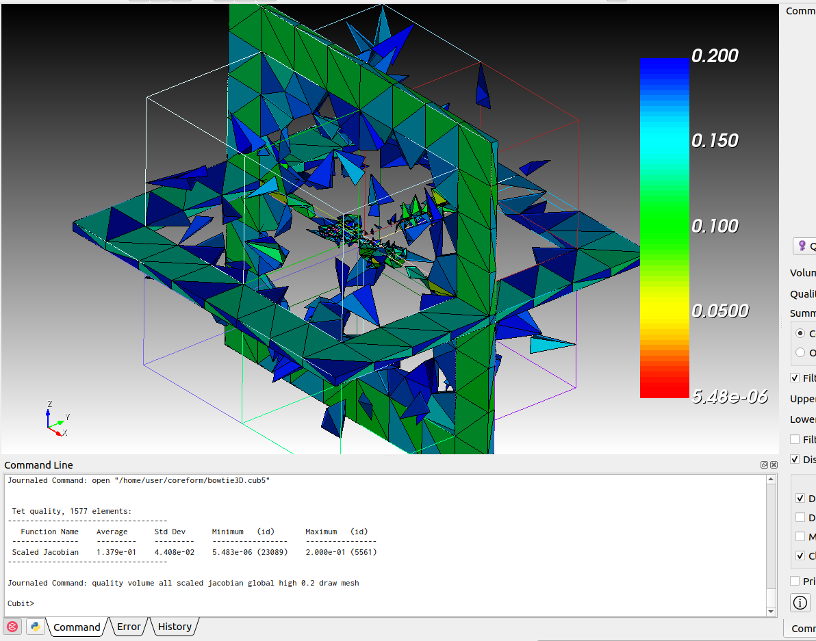
bowtie3D.cub5 (3.1 MB)
Please see the attached
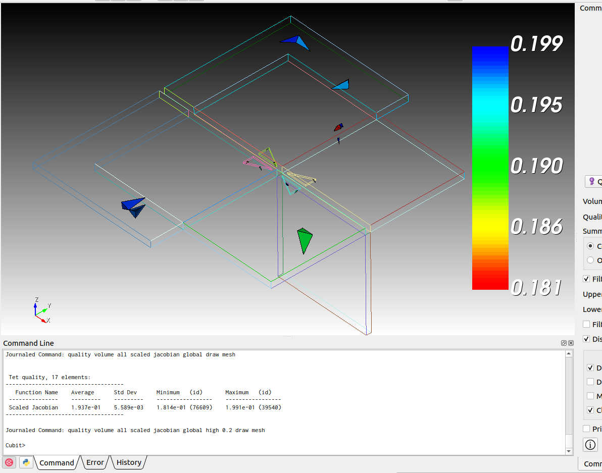
It seems like your desired mesh size is too coarse.
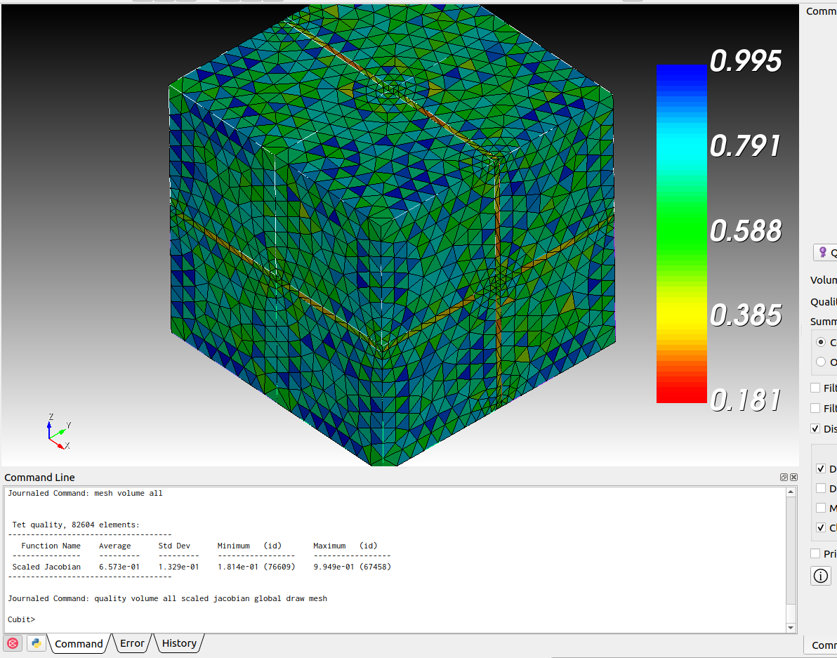
doing
delete mesh
vol all size auto factor 6
mesh vol all
quality volume all scaled jacobian global draw mesh
results in a lot better mesh quality then before.
Thanks a lot. Norbert. This command helps a lot.
I would like to confirm that webcut is the only way to the add that kind of node set, right?
In addition, I have a question about the excitation plane. The excitation plane and and another 2 prisms are united to a new volume, and then is subtracted from the inner box. With this, the excitation plane is still be included in the new volume(Vacuum in the cub file), right?
Thanks,
Xiaodong
Hi Xiaodong,
webcuts are not the only way but it’s probably the most easy way. You somehow need to have the curves topology available when you mesh. If not, the nodes won’t be created on the curves and you would need to search nodes near your curves for the nodeset. Which will probably be very inaccurate for a simulation if you need the nodes on a specific position.
Which volume/surface is your excitation plane in the cub?
Hi, Norbert,
Please see the attached, where the excitation plane is marked as a sideset. I used the following script,
create curve vertex 1 11
create curve vertex 12 4
create surface curve 15 19 4 20
brick x 100
unite body 1 3 2
subtract body 1 from body 4
sideset 28 add surface 23
sideset 28 name “Excitation”
The above operation, subtract, subtracted a volume (consisting of two prisms and an excitation plane connecting them) from the outer volume.
With this kind of subtraction, the excitation plane will still be meshed in the final volume right? But it is a little weird, because this excitation plane was subtracted from the outer volume.
What is the logic here?
Thanks,
Xiaodong
Geometry.cub5 (77.4 KB)
The topology from the plane won’t be ignored when you do a boolean operation. That’s why you end up with the surface in the new volume. If you don’t want this plane then don’t use the excitation plane for the boolean operation.
When you mesh a volume. Then first all vertices will be meshed. Then the curves and then the surfaces. After that, the actual volume will be meshed. So the mesher will take the excitation plane into account as it can’t just ignore a topology feature from the geometry.