
Hi, I am working on learning from the tutorial using the GUI, my question is where to click to mesh the volume with the tetrahedron.
Thanks!
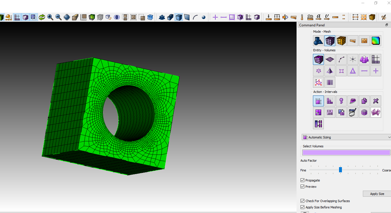
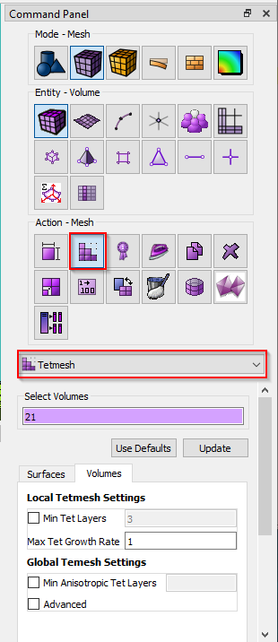
The next button over from the Sizing button allows you to define mesh schemes. One of the options on the pull down in that panel is Tetmesh.
You can also type the commands at the command prompt.
volume 1 scheme tetmesh
mesh volume 1
Thanks,
Karl
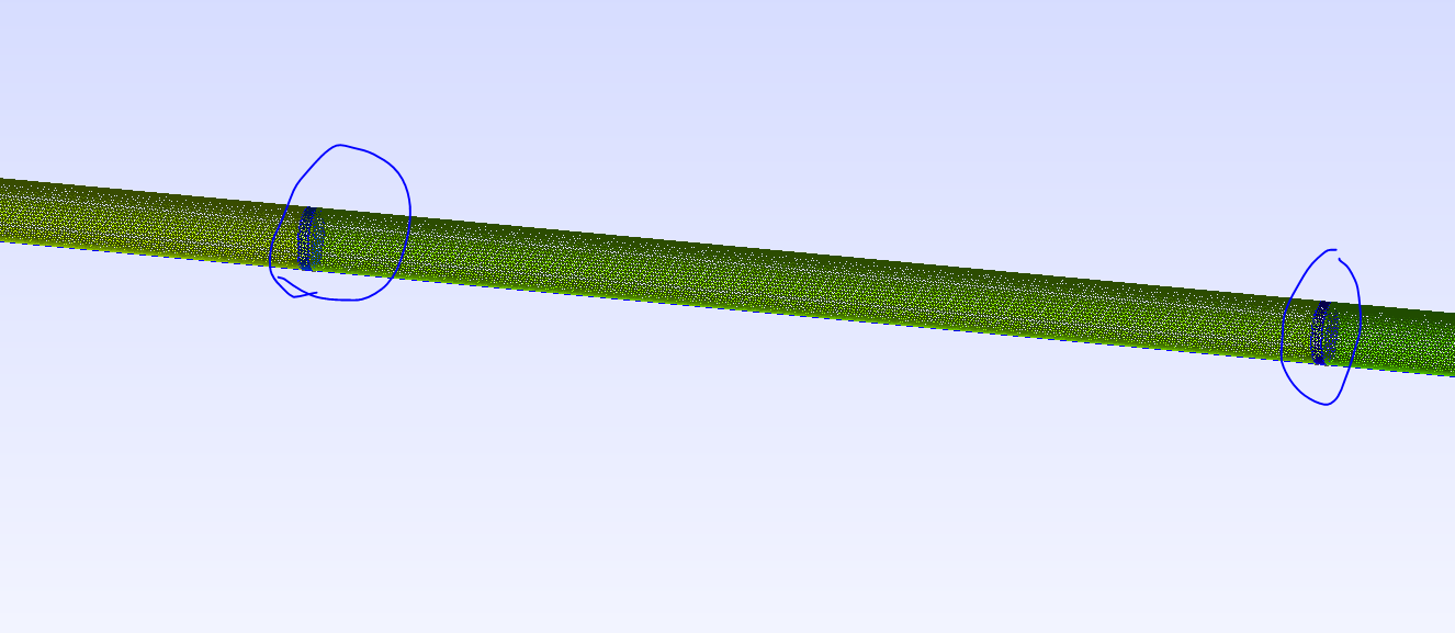
Thanks, Karl, a follow-up question, in Hex mesh, if I want to do the local grid refinement, from the tutorial, I click curves and then set a smaller size, then mesh the whole volume, but in Tet mesh, it won’t refine the whole surface, but in Hex it will, so how can I local grid refine the in Tet mesh?
And is there any way I can input my Gmsh.geo file into the Coreform, so I don’t need to learn from the beginning.
Hi, @miraboreasu1
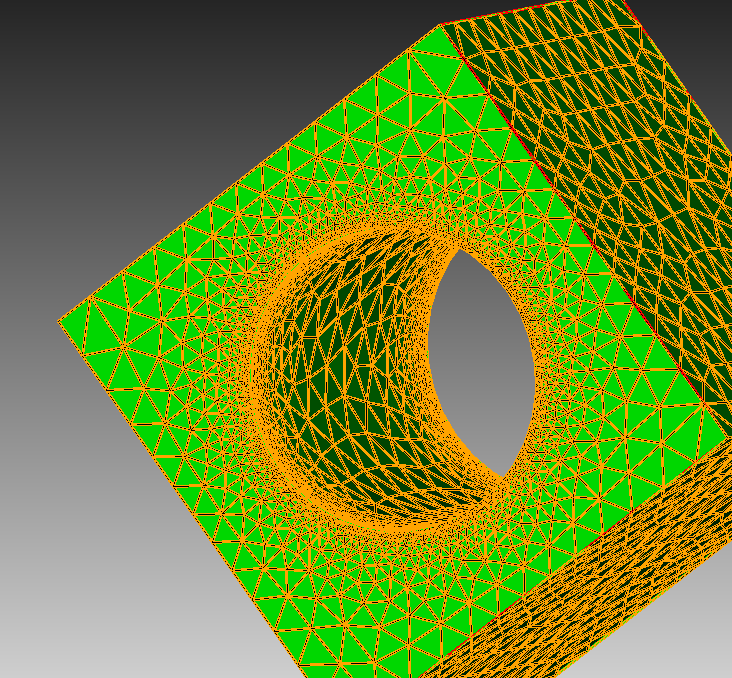
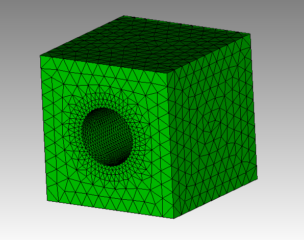
Does this image show what you are looking for? With a hex mesh the surface size is constrained by the curve size. That is not the case with a triangular mesh. In this case you have to set the size on the entire surface.
brick x 10
cylinder radius 2 z 12
subtract volume from 1
vol 1 scheme tetmesh
surface 10 size .25
mesh volume 1
We do not have a translator for the gmsh .geo file. If I had a large .geo file that I wanted to bring into Cubit, I would use Cubit’s python interface to recreate the .geo file.
Karl
@karl Sorry for another question, what I am doing now is I want a cylindrical empty space in a box
And the example you gave me works perfectly, but now I need to group some sub-cylindrical as surfaces and give them a name, so that the simulator can recognize them, like this I built in Gmsh
I think the best way to do it is to break the cylinder into pieces and pile them up one by one?
Sorry for the long note, can you show me an example of a cylinder containing a sub-cylinder and noteset as a surface?
Here is a script to do what I think you want. There are many ways of inscribing the surfaces inside the cylinder. I chose to create two temporary volumes and imprint the curves that touch onto the interior cylinder.
Here are the toolbar icons that I actually used.
![]() Transparent mode.
Transparent mode.
![]() Solid (smooth shaded) mode.
Solid (smooth shaded) mode.
![]() Graphics clipping plane on
Graphics clipping plane on
![]() Clipping maniplation widget on/off
Clipping maniplation widget on/off
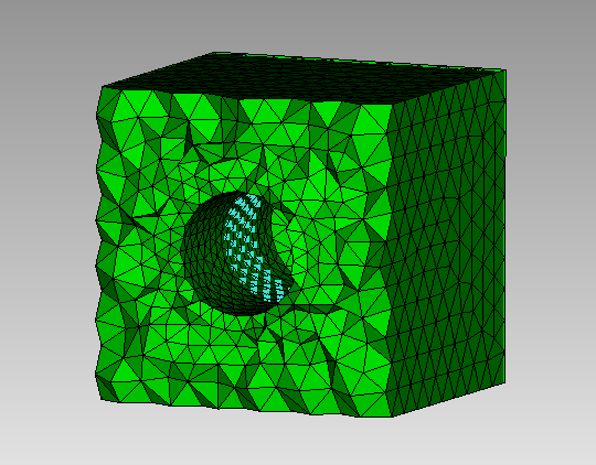
Note that Cubit does not normally draw the interior elements because the drawing sets can become immense. If you want to visualize the interior elements, you have to specifically draw them first.
reset
brick x 10 y 10 z 20
cylinder radius 2 z 15
subtract vol 2 from 1

graphics mode transparent # normally I use the transparent green cube in the toolbar
cylinder radius 2 z 2
vol 4 copy move z 5
vol 4 move z -5
imprint all
del vol 4 5
compress
nodeset 1 add surf 9 11
# Cubit provides a large set of tools for filtering geometry.
# See the documentation under "Controlling the Application/Entity Selection and Filtering"
draw surf with radius=2
surface with radius=2 size .5
vol 1 size 1
vol 1 scheme tetmesh
mesh vol 1
display
draw tet all
graphics mode smoothshade # normally I use the solid green cube in the toolbar

graphics clip on plane zplane # I normally use the toolbar buttons for these two functions
graphics clip manipulation off

draw nodeset 1 add
Karl
1 Like
BTW, I just noticed that I abbreviated some of the keywords. You don’t have to type them out if they are unique. Thus “vol” for volume or “del” for delete.
1 Like