Coreform Cubit Version: 2023.04 (the academic free license). Platform: Windows 10
Issue What can we help with?
Dear Community,
I am an absolutely newby in Cubit and need your help. I want to mesh a domain that has two bricks and two cylinders. Bricks are on top of each other and cylinders are also in one of the bricks. I want the mesh to be well refined in the cylinders and also in their adjacency. I want the mesh to be fine and increase the size gradually from the surface of the cylinders. Meanwhile, I want also to embed the cylinders in the brick. I tried the merge option but the mesh does not look like what i want and it looks the cylinders are not correctly embedded in the volume. My simple journal file is also attached. I very much appreciate any help.
Welcome to the forum! A common Cubit learning issue is giving the merge command more power than it actually has. Merging applies to adjacent surfaces that have the exact same topology. The cylinders inside the volume initially don’t have any surfaces that match those criteria.
Here are the changes I made to your journal file.
I did a boolean operation to subtract the cylinders from the surrounding material and make sure that I keep the cylinders around.
I did an imprint operation that makes sure that topologies are shared. Vertices and curves are imprinted onto adjacent surfaces in both directions.
I merged the volumes to make sure there is only one surface shared between adjacent volumes. This ensures a conformal mesh between the volumes.
I specified specific sizes on the cylinders and the surrounding volumes.
The kind of refinement you want is most easily achieved with a tetrahedral mesh. By default, Cubit will try to create a hexahedral mesh. I specified that I wanted a tetrahedral mesh on all volumes.
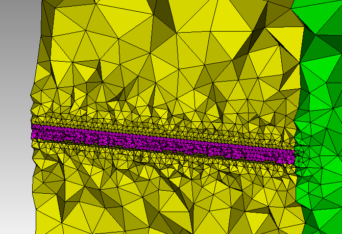
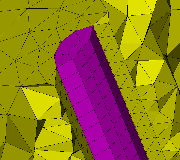
Here is a journal file that completes your process and a cross sectional mesh of the resulting tetrahedra.
Thanks,
Karl
reset
brick x 200 y 100 z 20
brick x 200 y 100 z 40
move Volume 1 z -10 include_merged
move Volume 2 z -40 include_merged
cylinder rad 1 height 40
move Volume 3  x -50 z -40 include_merged
cylinder rad 1 height 40
move Volume 4  x 50 z -40 include_merged
subtract volume 3 4 from volume 2 keep_tool
imprint all
merge all

volume 3 4 size 1
volume 1 2 size 10
volume all scheme tetmesh
mesh vol all

# These are the commands to create the image below.  I usually do with the graphics manipulation with
# the GUI. I included them here for completeness. Note that by default, Cubit does not draw internal
# elements. If we want to see the internal elements, we have to draw them.
draw tet all
graphics clip on plane X offset -50
graphics clip manipulation off

# use graphics clip off or the clip toolbar button to turn off clipping.
Huge thanks for your help and support.
Is is possible to mix hex and tets in cubit? My real domain has typically very big bricks (~ 10’000 x 10’000 x 1’000) with super thin cylinders with radius around 0.3. The cylinders are hot spots in my simulation and I need to refine around them but at the same time I should not exceed my budget. Do you know any efficient way in Cubit to mesh such a domain? Is it possible to make hex in thee cylinders and tet mesh in bricks?
Thanks again for your time.
The tetmesher in Cubit will automatically insert a layer of pyramids, before transitioning to tets, on surfaces that are meshed with quadrilaterals. Thus, if you first mesh the cylinders with hexes and then mesh the remaining volumes with tets, you’ll have a mixed mesh. Here’s a modification to @karl’s script that does this:
reset
brick x 200 y 100 z 20
brick x 200 y 100 z 40
move Volume 1 z -10 include_merged
move Volume 2 z -40 include_merged
cylinder rad 1 height 40
move Volume 3  x -50 z -40 include_merged
cylinder rad 1 height 40
move Volume 4  x 50 z -40 include_merged
subtract volume 3 4 from volume 2 keep_tool
imprint all
merge all

# mesh the cylinders with hexes
volume 3 4 size 0.5
surface 14 15 17 18 scheme circle
mesh volume 3 4

# meshing the blocks with tets will now use pyramids to transition from hex->tet
volume 1 2 size 10
volume all scheme tetmesh
mesh vol 1 2

# These are the commands to create the image below.  I usually do with the graphics manipulation with
# the GUI. I included them here for completeness. Note that by default, Cubit does not draw internal
# elements. If we want to see the internal elements, we have to draw them.
draw tet all pyramid all hex all
graphics clip on plane X offset -50
graphics clip manipulation off

# use graphics clip off or the clip toolbar button to turn off clipping.
hi @gvernon
Thanks a lot for your help. I do appreciate your time.
I tried to make some physical groups based on the script your prepared. There is one issue with them. In Cubit for example I assign volume 1 as "cap" but when I go to my solver it does not know ''cap'' because I have cap_TETRA and cap_PYRAMID5 in my mesh. Is there any trick to avoid the separation of them?
Another question is that is there any more efficient way for refinment? I am still above the limits. Can I have hex in all my domain and still make a gradual refinement from cylinders? In the following I copied the journal file I used:
reset
brick x 200 y 100 z 10
brick x 200 y 100 z 20
move Volume 1 z -5 include_merged
move Volume 2 z -20 include_merged
cylinder rad 0.5 height 20
move Volume 3 x -50 z -20 include_merged
cylinder rad 0.5 height 20
move Volume 4 x 50 z -20 include_merged
subtract volume 3 4 from volume 2 keep_tool
imprint all
merge all
# mesh the cylinders with hexes
volume 3 4 size 0.4
surface 14 15 17 18 scheme circle
mesh volume 3 4
# meshing the blocks with tets will now use pyramids to transition from hex->tet
volume 1 2 size 50
volume all scheme tetmesh
mesh vol 1 2
block 1 add volume 1
block 1 name "cap"
block 2 add volume 2
block 2 name "res"
block 3 add volume 3
block 3 name "hot_leg_vol"
block 4 add volume 4
block 4 name "cold_leg_vol"
sideset 5 add surface 13 14 15
sideset 5 name "hot_area"
sideset 6 add surface 16 17 18
sideset 6 name "cold_area"
sideset 7 add surface 4 10
sideset 7 name "left_side"
sideset 8 add surface 6 12
sideset 8 name "right_side"
sideset 9 add surface 3 9
sideset 9 name "front_side"
sideset 10 add surface 11 5
sideset 10 name "back_side"
sideset 11 add surface 1
sideset 11 name "top_side"
sideset 12 add surface 22
sideset 12 name "bottom_side"
draw tet all pyramid all hex all
graphics clip on plane Y offset 0
graphics clip manipulation off