Coreform Cubit Version:2022.4)
Platform: win11
Issue
Dear all,
I want unmerge the surface in volume, but always get no entities, how can I mesh all and unmerge the surface inside of volume?
Thank you very much!
shineusn.cub (8.0 MB)

Coreform Cubit Version:2022.4)
Platform: win11
Issue
Dear all,
I want unmerge the surface in volume, but always get no entities, how can I mesh all and unmerge the surface inside of volume?
Thank you very much!
shineusn.cub (8.0 MB)

Hi,
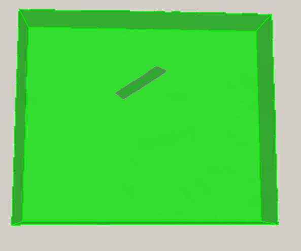
Welcome to the forum. Merging and unmerging have very specific meanings in Cubit. Surface 17 is embedded in Sheet Body 3, and it is not currently merged in the model. Merging is done on coincident surfaces, curves, and vertices. You cannot merge or unmerge (in the Cubit sense of the words) the two bodies in your model.
The easiest thing to do in this case is to do a Boolean operation between the two parts.
subtract body 3 from volume 1
vol 4 scheme tetmesh
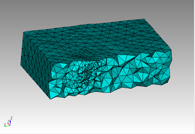
Surface 18 size 1500 # make the fault mesh denser so we can see it in the tetmesh
mesh vol 4
draw tet all
# turn on the clipping plane
If you have more complex faults, especially some that intersect both top and the bottom of the surrounding volume, you may have to mesh the faults first and then use the tetmesh respect option.
surface 17 scheme trimesh
surface 17 size 1500
mesh surf 17
vol 1 scheme tetmesh
vol 1 tetmesh respect tri in surf 17
mesh vol 1
The results will be slightly different but both methods will give a valid tet mesh in this case.
Karl

Dear Karl,
Thanks a lot, I tried to mesh and successfully, if I want to unmerge the inner faces? How should it be modified?Or how to divide the inner surface into two layers (may be a little different vertex) ?
Thank you!
Hi @shineusn,
I have created a video showing how to create a double-sided surface with Cubit. This will create a slip plane. Depending on your analysis code, you might also have to create a contact boundary condition between the nodes on the two surfaces. The process is a little involved because we are asking the tet-meshing algorithm to ignore some of the built-in optimizations that it would normally use.
The basic steps to create a mesh that allows for slippage are as follows.
As this is quite involved, I created a 5-minute video that shows the techniques required to create disconnected tetrahedra on the fault plane.
Thanks,
Karl
Dear Karl,
I tried this method and it works now, really huge help.
thank you very much!
Hi Karl,
This is very nice way to generate tetrahedral elements. Is there any way to do hexahedral elements for double sided fault surface? I’m trying sculpt, but it does not work well so far.
Thanks in advance.
Best,
Qingjun
Hi Qingjun,
I have never tried doing double sided surfaces in sculpt. I will have to see if that is even supported. In a typical hex mesh, you can’t just insert a surface and hex mesh around it. You will have to modify the topology so that the surface is part of a volume that can be hex meshed.
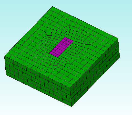
In the example below, I swept the surface surface through the other geometry to create two volumes. The inner volume can be represented with a mapped mesh and the outer volume is a one-to-many swept mesh. I did the imprint and merge steps to create a conformal mesh. Then I unmerged the surface. Note that this unmerge kept the boundary nodes merged and just unmerged the interior nodes.
As an example,

reset
brick x 150 y 150 z 50
create surf rectangle x 20 y 20 z 20
create surf rectangle width 50 height 20
webcut volume 1 sweep surface 7  perpendicular outward through_all
delete vol 2
volume 3 size 3
volume 1 size 10
imprint all
merge all
unmerge surf 12

Surface 13 scheme pave
mesh vol all

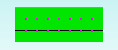
topology check coincident node node all tolerance 1e-06 draw brief result group
draw coincident_nodes
draw surf 12 add

Thanks,
Karl
I have a similar situation, but I don’t want to unmerge the nodes. However, I need two sidesets–one for each side of the slip surface. I get errors when trying to make sideset for the reverse side of the surface. Is this a problem because there is no obvious outward normal for this surface? Thanks!
Thank you for your response! Is there a way to attach files to this board? I’m new here! I’m afraid that the surface I’m using is a result of a rather complicated importing process.
Thank you! I’ve uploaded the mesh that I’m importing (purely to get the fault surface from it, and then delete the rest of the mesh), as well as a text file of the commands I’m using in Cubit. Thank you very much or any advice you can give me.
https://transfer.coreform.com/n3ONnC1axA/CherryHillMeshingTest_100mAt2km1000mAt10km_shell.inp
https://transfer.coreform.com/9EIL8aAahr/ImportMakeACIS_justfault_bufbox_flexible.txt
I should mention that one issue I see is that when I try to select a vertex on the fault surface after meshing, I get a message saying:
ERROR: Surface 54 has bad sense information with respect to volume 14
Probably is a 2-sided surface embedded in volume 14
Cannot handle this case.
Subsequently, I want to assign 2 sidesteps to this surface, in the forward and reverse direction. When I do so, I get the warning:
WARNING: Assigning unmerged surface 54 to Sideset 8 with
BOTH or REVERSE sense.
WARNING: This usually means that either the surface needs to be merged
or you need to assign shell elements.
Finished Command: sideset 8 surface 54 reverse
The fault surface is a non-manifold surface in the volume. Cubit is having problems dealing with that non-manifold surface. The method that I typically recommend for dealing with faults is to mesh them first and then use the tetmesh respect option to insert the triangles into the mesh.
The following journal file demonstrates the method on the just the fault area. I still do an imprint and merge to get the fault line on the top surface. Also, I would avoid using the skeleton sizing function. The default trimesh and tetmesh algorithms both include auto sizing. Note that the fault is at size 100 and the bounding volume is size 300.
Also, to get the sidesets to show up in Paraview I had to place the fault in a separate block. Exporting to Abaqus, the side ELSETs were present without requiring a separate block. I don’t think you should need the block for your analysis code.
The image below shows the dense mesh around the fault transitioning to a somewhat coarser mesh at the boundary.
And sideset 9 (the cub5 file still contains references to the prior sidesets)
The start point is here: https://transfer.coreform.com/990pQSzmqM/sidesets.cub5
Hope this is helpful,
Karl
reset
open "~/sidesets.cub5"
imprint all
merge all
surf 13 scheme trimesh
surf 13 size 100
vol 14 scheme tetmesh
mesh surf 13
vol 14 size 300
vol 14 tetmesh respect tri in surf 13
mesh vol 14
block 1 vol 14
block 1 element type tetra
#block 2 surf 13
#block 2 element type trishell
sideset 9 add surface 13 forward
sideset 10 add surface 13 reverse
export mesh 'fault.g' over
Thank you so much! I will definitely give this a try.
–David
Actually, I’m still getting the following error when trying to define the reverse sideset:
WARNING: Assigning unmerged surface 13 to Sideset 10 with
BOTH or REVERSE sense.
WARNING: This usually means that either the surface needs to be merged
or you need to assign shell elements.
Finished Command: sideset 10 add surface 13 reverse
I suspect this is going to be problematic for my FE code. Is there a way around this? Thanks!
–David
Which code are you using? As Karl said, the abaqus export contains the sidesets with SPOS and SNEG.
The warning just tells us that you are assigning a surface sense for faces that aren’t shell elements. And that is correct.
If you create a block and assign shell elements for the surface prior to creating the sidesets. Then there will be no warning message.
Those are the 2 commented lines in the above journal.
#block 2 surf 13
#block 2 element type trishell
Thanks, Norbert (and Karl)! OK–so it may be that it’s my analysis code that just has a problem with the way the sidesets are defined. Basically, my code (FaultMod, by Michael Barall) is telling me that the positive and negative sidesets are containing faces from the same side of the fault.
You may try using the both option instead of the two open/reverse. Replace the forward/reverse lines with
sideset 9 add surface 13 both
Is FaultMod reading the Exodus II mesh? You may need to add the trishell block as well. As I mentioned, that was required for Paraview visualization of the Exodus mesh.
Karl
Cool–I’ll try both options. Thanks!
–David