Ive got a geometry that meshes fine with tets, and seems to mesh fine with sweep-target on hex, looking at the mesh in Trelis, however when I export that mesh to exodus, the resultant mesh is incorrect. Happy to share the inputs if that helps.
Are you able to share the inputs? If so I can take a look at this. It will be easiest for me if you can send me your Trelis file containing the geometry and a journal file used to make the mesh.
Sorry its taken me so long to get back to you! The exodus file is large, could you please reach out with your email address and I’ll share a link to the exodus file.
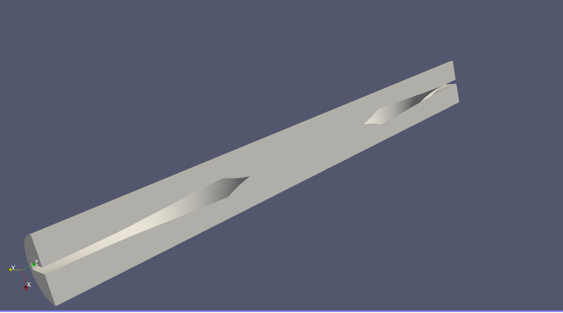
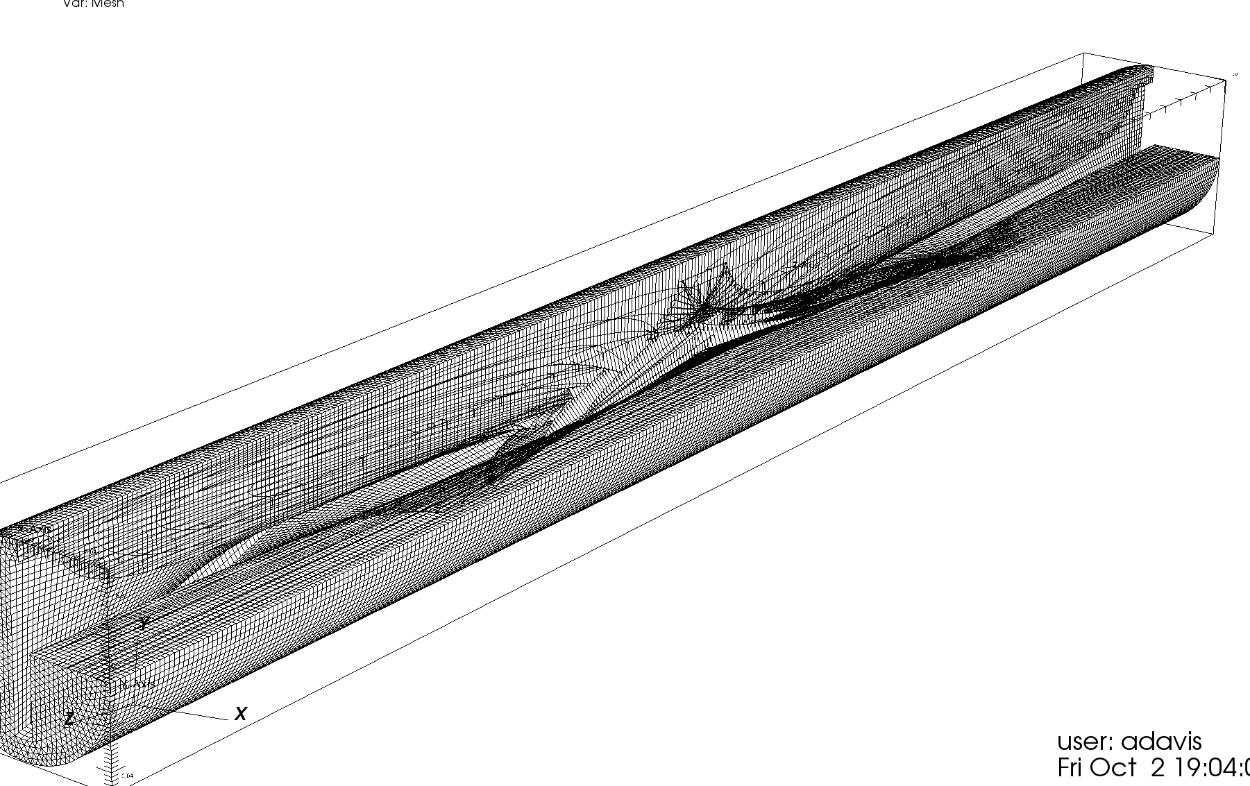
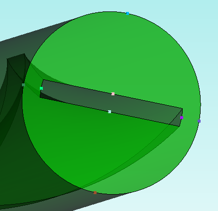
What my investigations have shown (I think) is that the mesher meshes it correctly, but in writing it to an exodus file, it is somehow corrupted. The hex mesh is displayed correctly in Cubit/Trelis when meshed, but when I import that exodus file into Trelis or Visit/Paraview it appears corrupted as above.
You cant tell, but this is the mesh clipped after just being produced or reimported from the .cub file. So im confident that its either a bug in the exodus export. Ill try sending to another format, say openfoam, or abaqus and see if i can visualise it correctly that way.
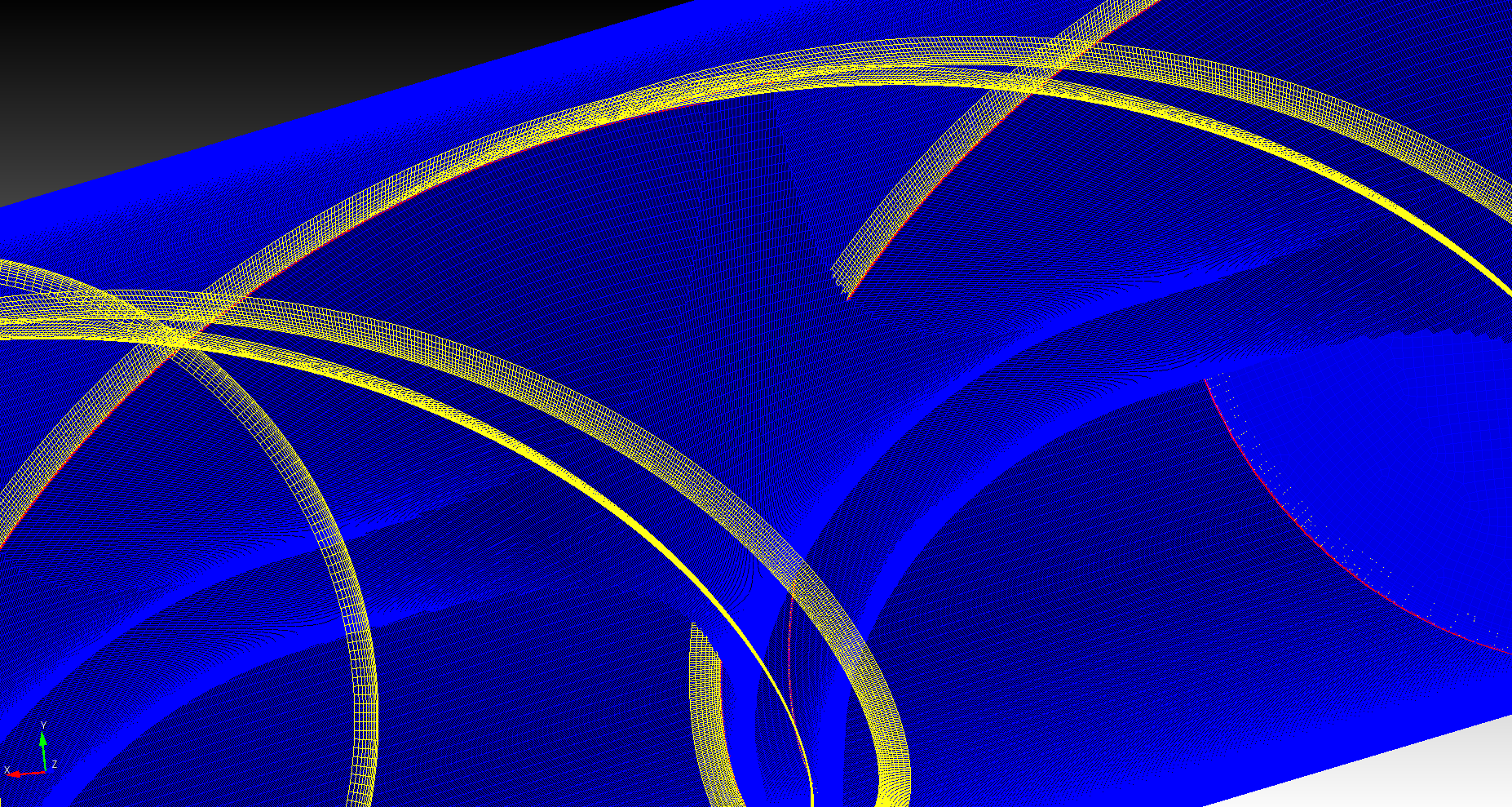
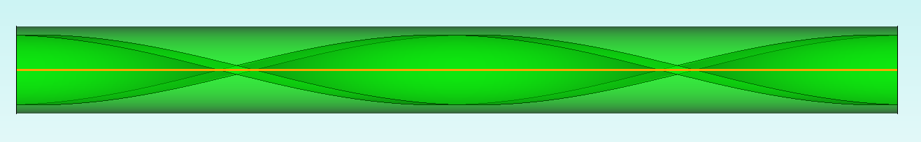
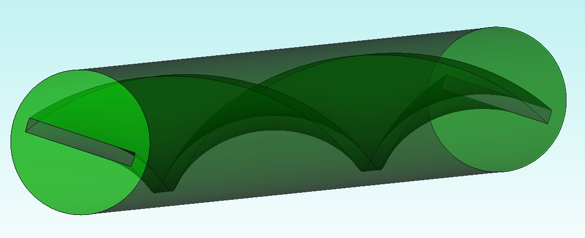
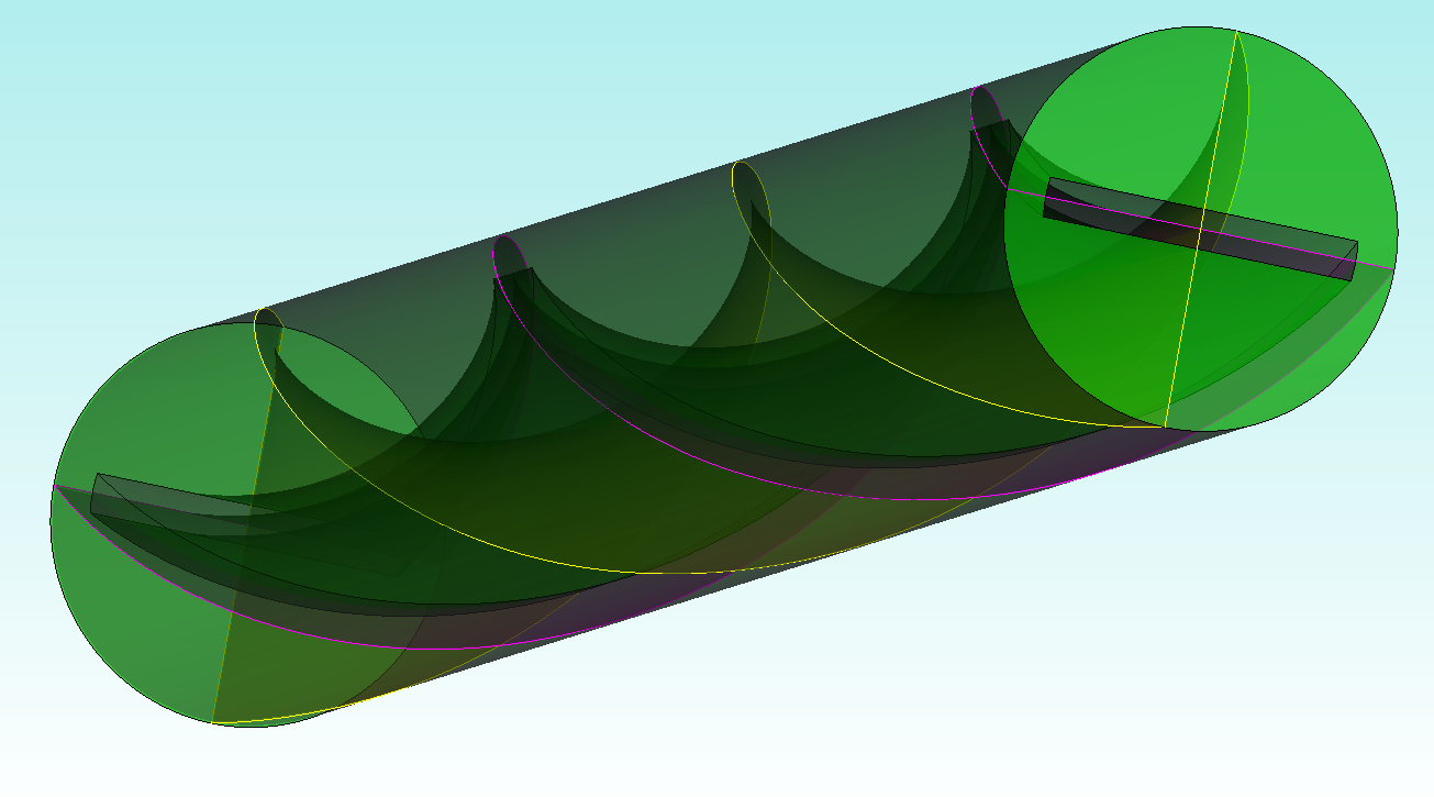
Essentially, this will cause elements to invert in order to respect both this straight curve and the tortuous curves inside the volume.
Volumes with a lot of “twist” often require a bit more assistance (in the form of webcut/partitioning) from the user to assist Cubit in laying down a valid mesh
Here’s a journal file that runs the commands, starting from the Trelis file you’ve sent:
## Open the file
reset
open "C:/Users/Owner/Downloads/swirly-hex.trelis"
## Delete mesh entities
delete mesh
delete boundary_layer all
## Block type was TETRA... change it to linear hexes
block 2 element type hex8
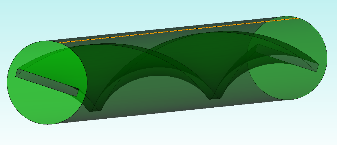
## Remove the extraneous, straight curve that will cause problems
compress ids
regularize vol 1
compress ids
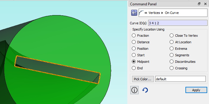
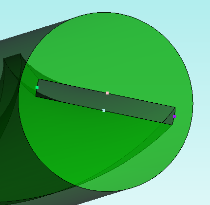
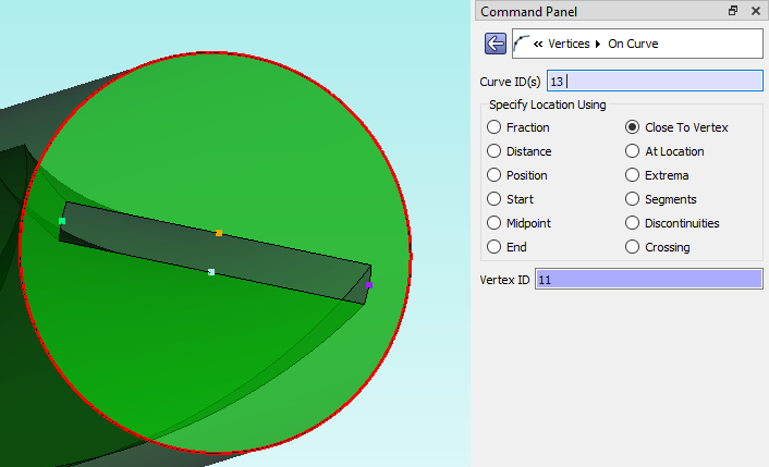
## Create vertices on / near midpoints of the rectangular feature
create vertex on curve 3 4 1 2 midpoint
create vertex on curve 13 close_to vertex 11 12 13 14
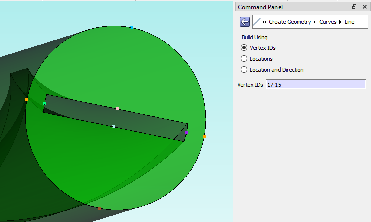
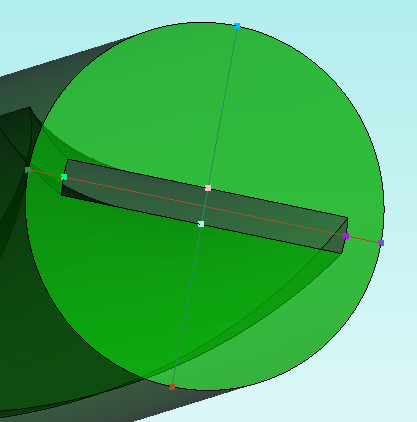
## Create curves to be used for cutting the geometry
create curve vertex 15 17
create curve vertex 16 18
## Sweep the curves along helical path to form cutting surfaces
sweep curve 15 along curve 6
sweep curve 16 along curve 6
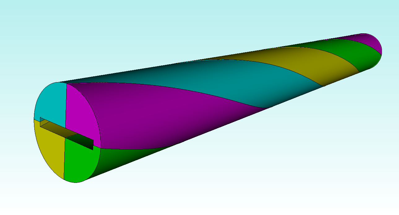
## Perform Webcuts
webcut Volume 1 tool Body 2
delete Body 2
webcut Volume 1 4 tool Body 3
delete Body 3
## Delete the free vertices we used for constructing the cut surfaces
delete vertex all
compress ids
## Imprint and merge volumes
imprint all
merge all
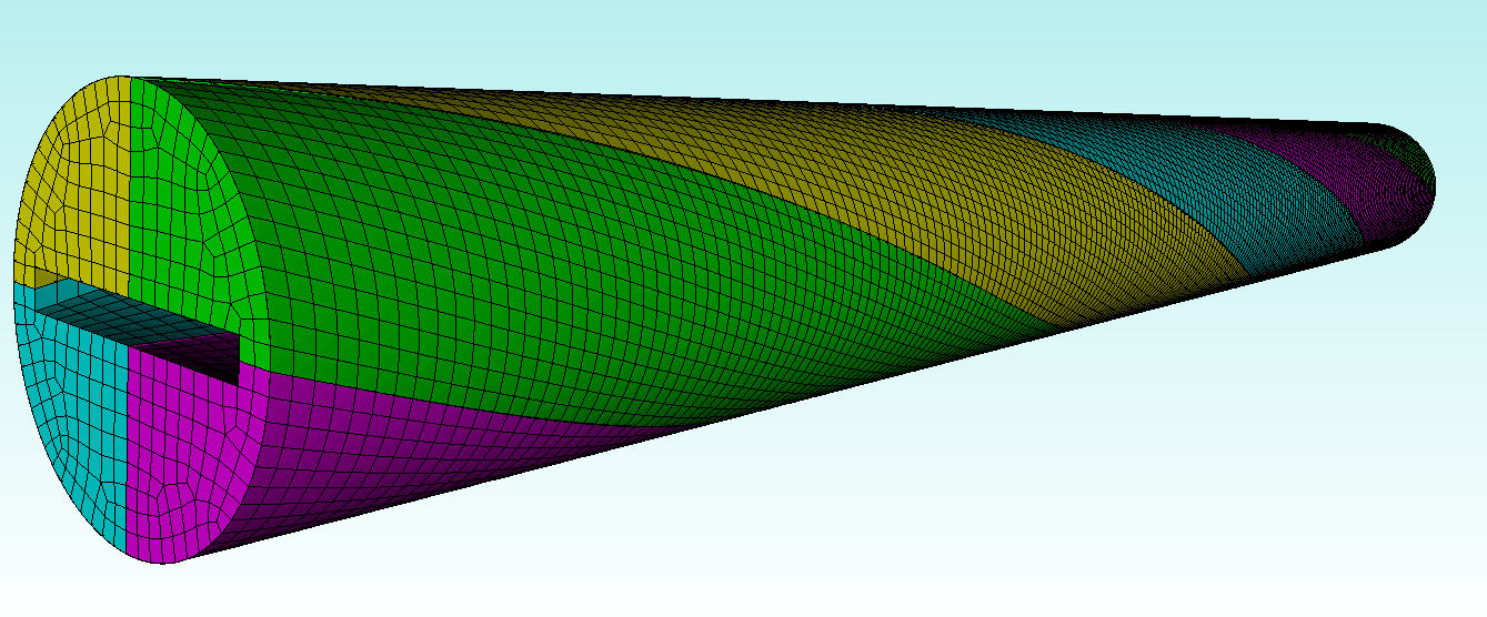
## Demo Mesh
vol all size 0.005
mesh vol all
Thanks Greg! Super helpful, thanks for that. Out of curioisty, how does one view the mesh as in the last plot? A regular ‘slice’ does not give me that view.