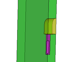
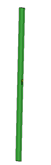
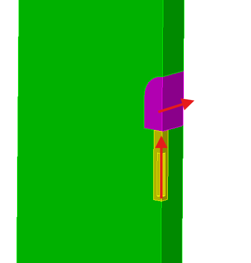
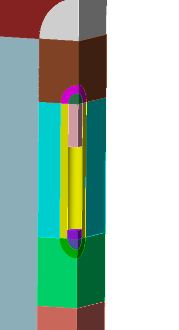
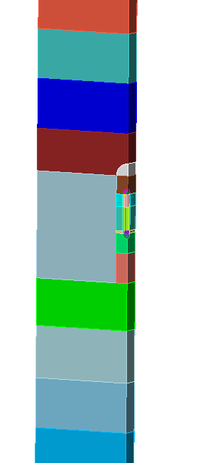
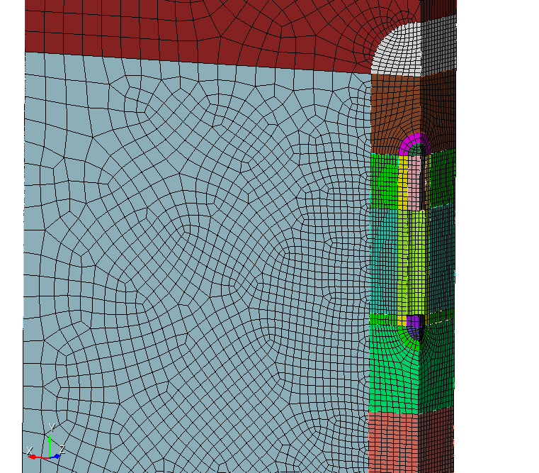
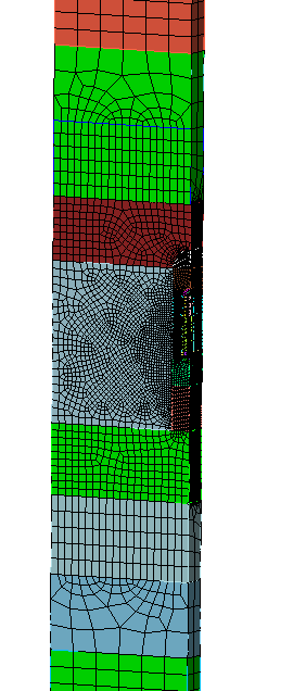
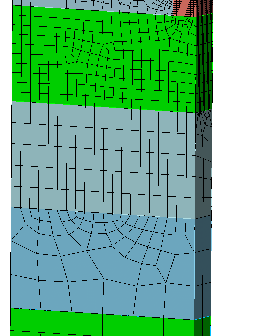
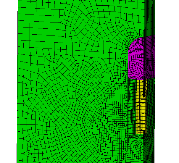
I took your journal and added a few lines. On top i set the geometry engine to acis. At the bottom i created a block for each volume. That is our starting point to do some decomposition.
#!cubit
reset
set Geometry Engine acis

create brick x 20 y 400 z 3.75
move volume 1 x 10 y -500 z 1.875
create cylinder height 7.83 radius 1.11
rotate volume 2 about x angle 90
move volume 2 y -496.085

create cylinder height 4.83 radius 0.61
rotate volume 3 about x angle 90
move volume 3 y -497.085

create brick x 2.5 y 3.65 z 3.75
move volume 4 x 1.25 y -490.345 z 1.875


create cylinder height 3.75 radius 2.5
move volume 5 x 0 y -488.52 z 1.875


section volume 2 3 with xplane
section volume 2 3 with zplane
section volume 5 with xplane
section volume 5 with yplane offset -488.52

unite volume 4 5

volume 2 copy
volume 4 copy
subtract volume 6 7 from volume 1
subtract volume 3 from volume 2

compress

block 1 add vol 1
block 2 add vol 2
block 3 add vol 3
When i take a look at how i would do a sweep if they were single volumes, i notice their crossing sweep directions. So i will try to aim for a decomposition that will let me use the polyhedral scheme to handle the crossing sweeps.
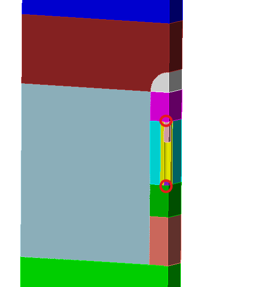
The first webcuts i do are as follows.
webcut volume all with plane yplane offset -510
webcut volume all with plane yplane offset -480
webcut volume 3 4 with plane normal to curve 13  fraction 0 from start
webcut volume 4  with plane normal to curve 14  fraction 0 from start
webcut volume 4  with plane normal to curve 74  fraction 0 from end
webcut volume 9  with plane normal to curve 74  fraction .4 from end
webcut volume 2  with sheet extended from surface 22
What i want to do next is to create a hollow sphere and use it as tool.
create sphere radius 1.11 inner radius 0.61
move Volume 13 location vertex 18  include_merged
webcut Volume 9 tool Body 13
move Volume 13 location vertex 14  include_merged
webcut Volume 3 tool Body 13
delete volume 13
Then i need a few cuts more to make the meshing easier and we can already imprint and merge everything.
webcut volume 1  with plane normal to curve 66  fraction 0.05 from end
webcut volume 4 2  with sheet extended from surface 23
webcut volume 19 20  with sheet extended from surface 24

webcut volume all with plane yplane offset -530
webcut volume all with plane yplane offset -470
webcut volume all with plane yplane offset -540
webcut volume all with plane yplane offset -460

imprint all
merge all
To be able to mesh we will need to set some schemes and take control over the meshing order. The size can also be set.
Volume 17 3 16 4 21 19 14 9 15 12 20 22 11 2 6 10 size 0.2
Volume 17 3 16 4 21 19 14 9 15 scheme polyhedron
mesh volume 3, 16, 17
mesh volume 4 14 19 21
mesh vol 9 15
Volume 2 22 20 scheme map
mesh volume 2, 20, 22
mesh vol 11 12

volume 6  redistribute nodes off
volume 6  scheme Sweep  source surface 53    target surface 52   sweep transform least squares
volume 6  autosmooth target on  fixed imprints off  smart smooth off
mesh vol 6 10


volume 1 7 8 size 1
Surface 61 68 132 scheme pave
mesh Surface 61 68 132
volume 8  redistribute nodes off
volume 8  scheme Sweep  source surface 68    target surface 67   sweep transform least squares
volume 8  autosmooth target on  fixed imprints off  smart smooth off
mesh volume 8

volume 1  redistribute nodes off
volume 1  scheme Sweep  source surface 132    target surface 130   sweep transform least squares
volume 1  autosmooth target on  fixed imprints off  smart smooth off
mesh volume 1
mesh volume 7

vol 5 23 size 2
Surface 194 190 scheme pave
mesh vol 5 23

vol 24 25 size 3
surface 214 212 scheme pave
mesh vol 24 25

mesh vol all
With the use of the pave scheme we are able to coarsen the mesh more.
As we put our starting volumes into blocks before the decomposition, we are now able to easily export them as single blocks/element sets if we want to.
draw block all
I hope this gives you some ideas how to handle such geometry.