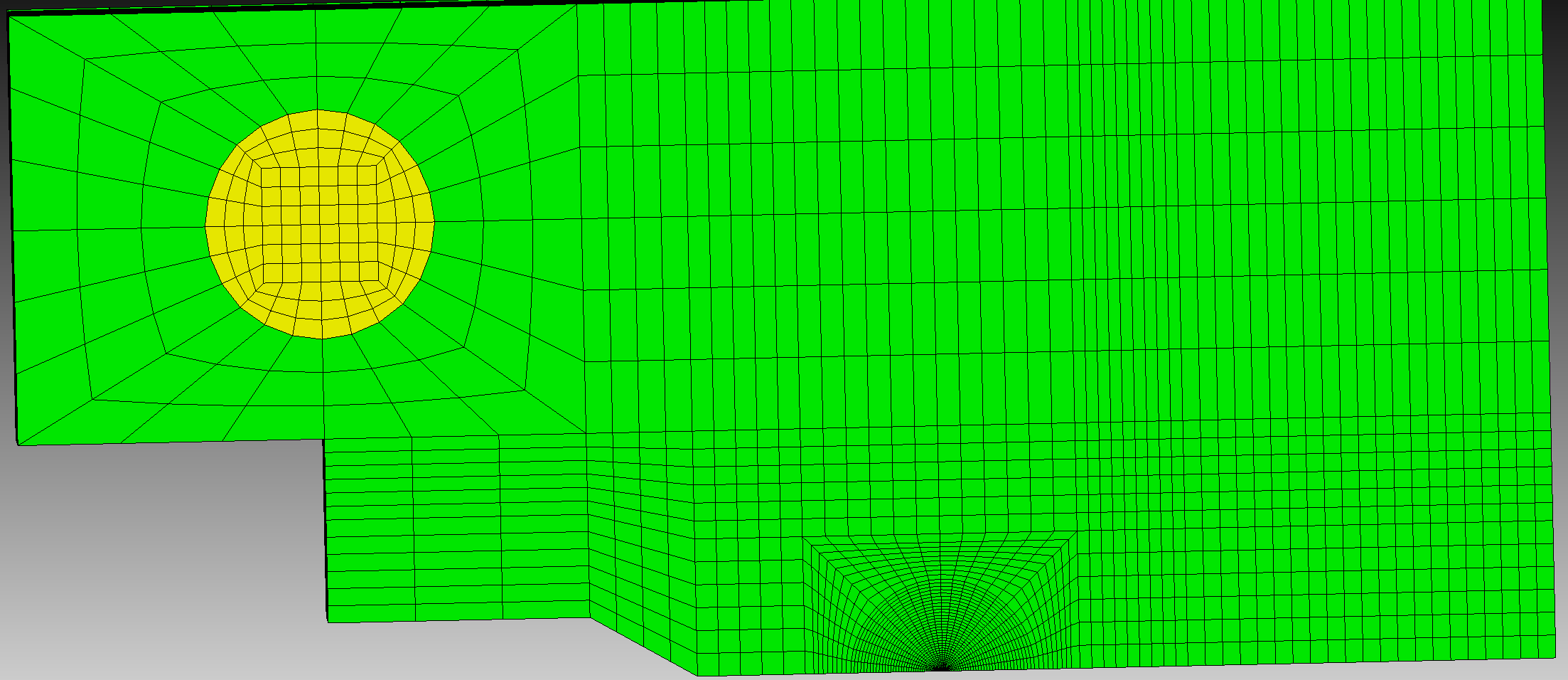
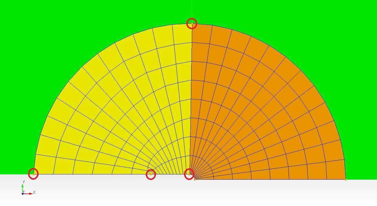
I have geometry with a blunt crack tip, model as semi-circle (quarter circle for symmetry model). I want to use a radial mesh around this blunt crack. I want the mesh to look similar to what other people are doing (see attached geo1.png) .
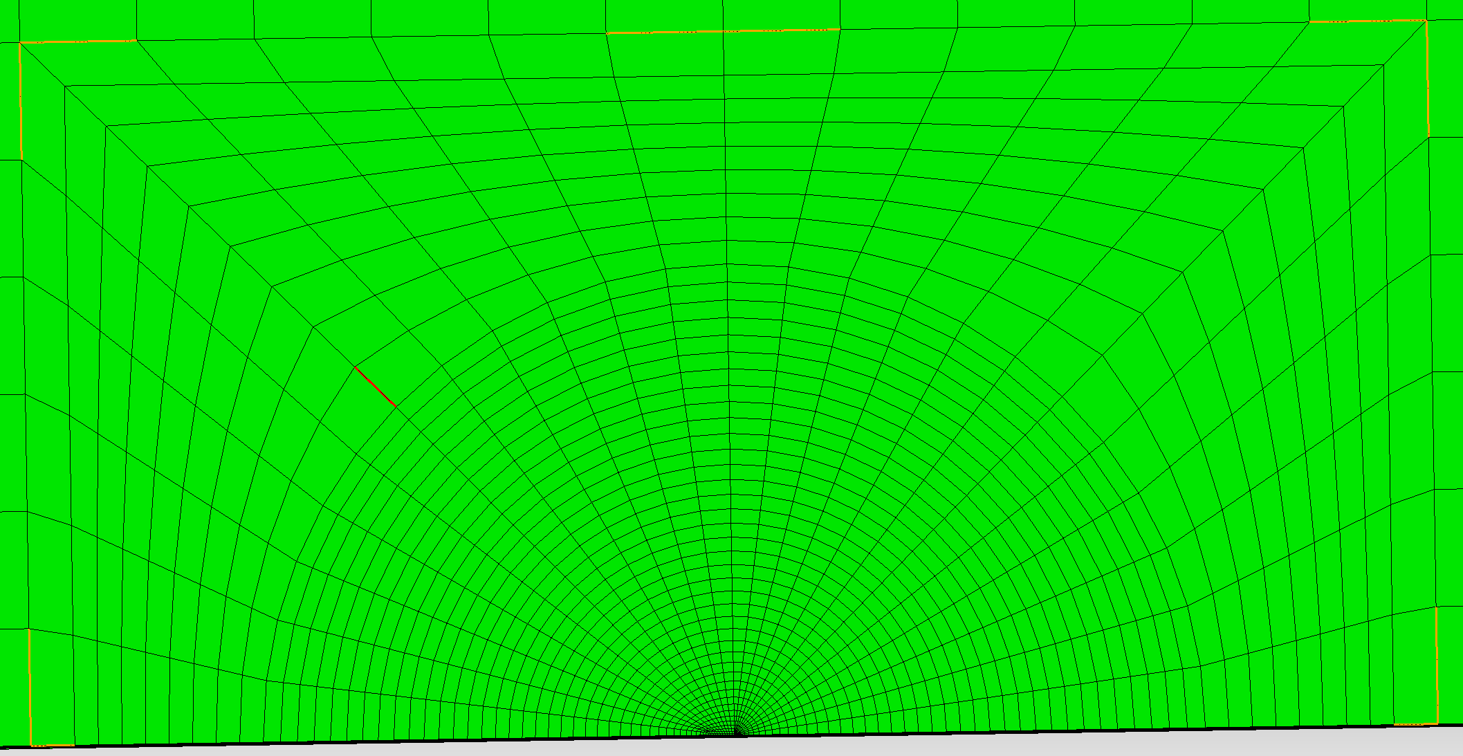
I understand that a square is drawn around the blunt crack tip. Then this square and area around the blunt crack is decompose to “fan” parts. These parts is then mesh using the mapping scheme (see attached geo2.png)
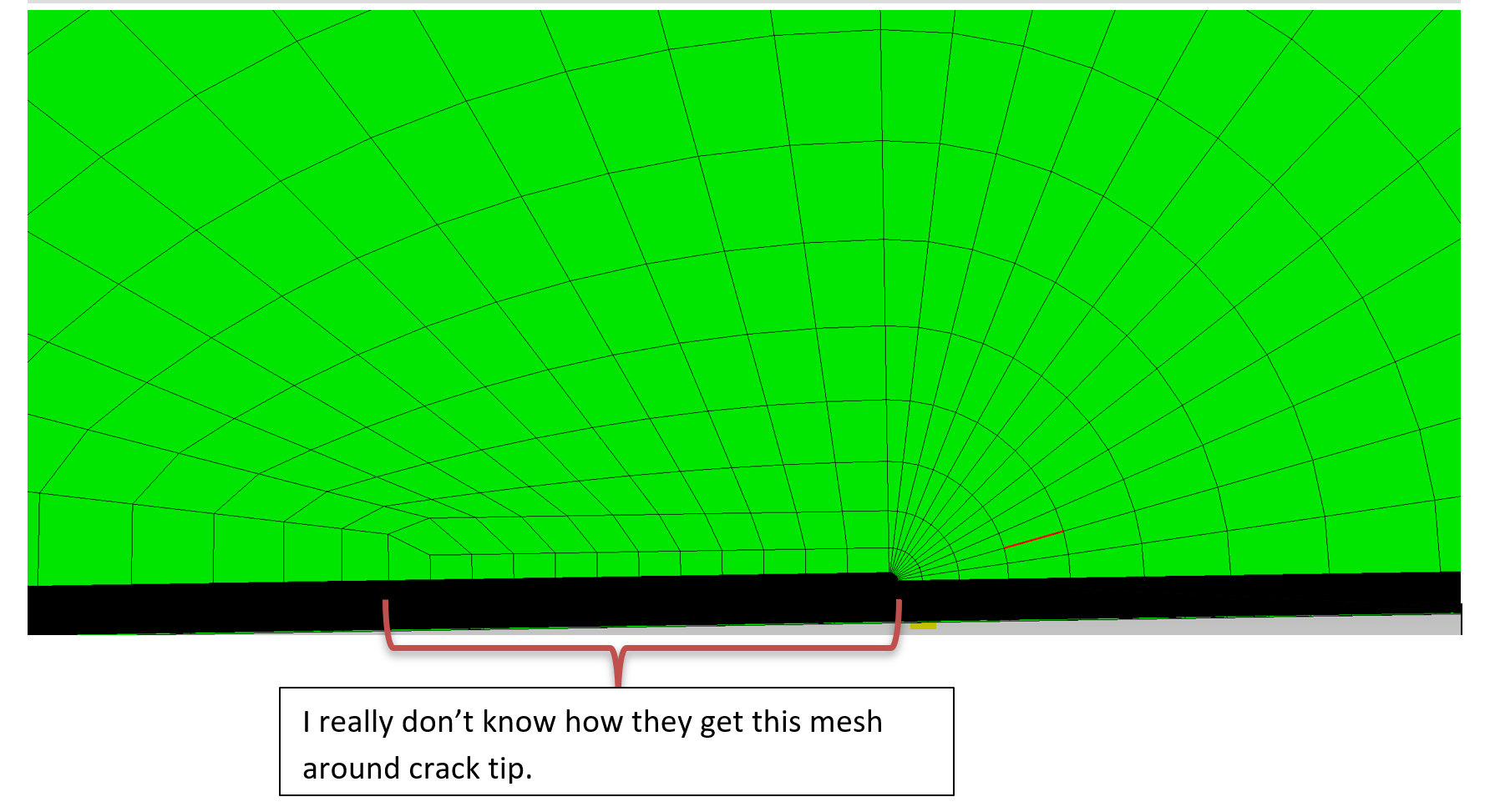
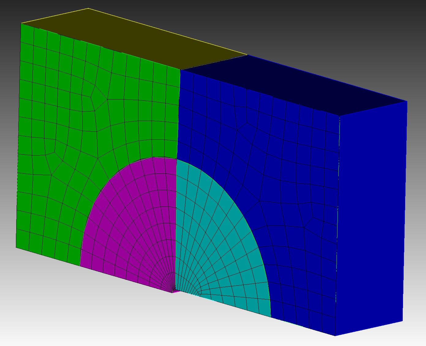
I don’t know how they get this nice mesh radially surround the blunt crack tip see geo3.png for one type
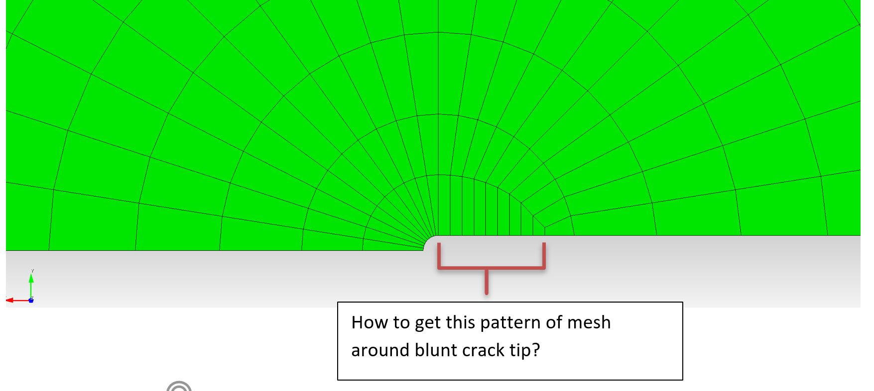
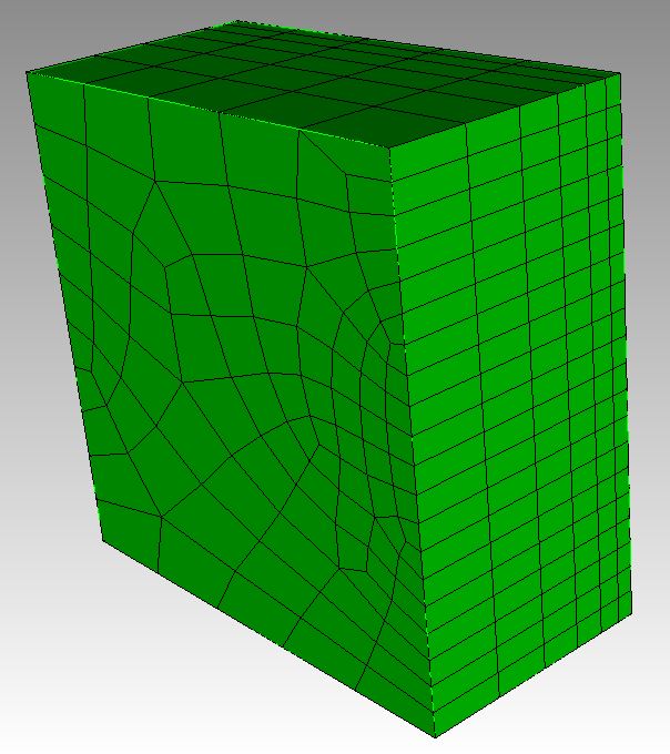
and geo4.png for another type.
Any tips of how to get this type of mesh around the blunt crack will be much appreciated. How to do it and what is the best way to do it?
One way to do this is to create four sides and map the surface. In my picture, the orange surface already has four curves, so a map scheme works. For the yellow surface, I split the bottom curve at an arbitrary location to create a fourth curve so that the surface can be mapped.
Here is an example
reset #Create the model
create surface rectangle width 10 height 5 zplane
create vertex on curve 3 midpoint
create surface circle radius .1 zplane
create surface circle radius 3 zplane
move Surface 2 location vertex 5 include_merged
move Surface 3 location vertex 5 include_merged
subtract surface 2 from surface 1
imprint surface 4 with curve 6
del surf 3
create vertex on curve 1 close_to vertex 5
create vertex on curve 7 close_to vertex 12
create vertex on curve 2 distance .1 from vertex 3
create curve vertex 13 14
imprint surface 5 6 with curve 15
del curve 15
del surface 9 10
create vertex on curve 1 close_to vertex 15
split surface 7 8 through vertex 15 18
del vertex all
#Split the bottom curve and set intervals
split curve 16 distance .75 from vertex 15
curve 17 25 28 31 interval 12
mesh surface 12 13
Thanks for the help. Now I am trying to turn this 2-D mesh into a solid 3D. I was able to do this by using the Sweeping surface (include mesh and merge) perpendicular distance. Is there any way to control the mesh seed distribution in the 3rd direction (ie when sweeping into the 3rd direction, I want a biased slices or a specified equal intervals)?