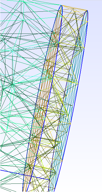
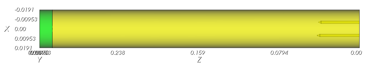
Hey Karl, sorry for posting a question again, I am trying to switch from GMSH to here. Now I am creating a big cylinder with two inlets (empty inside the cylinder, each of inlets is formed by two frustums which are stacked tightly, namely, the top r of frustum 1 is the same as the bottom r of the frustum 2, )
-
So I first create the cylinder, assume it is volume 1, and then create two frustums (volume 2 and 3), the two frustums are moved to be stacked tightly, and then I subtract them from volume 1
-
Do the same for another two frustums (volumes 4 and 5).
-
Then do the local grid refine around the empty part of the cylinder, namely, the subtracted four frustums
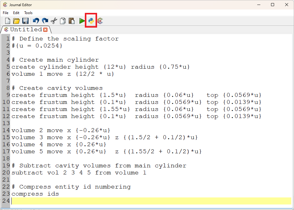
But the error happened on my first definition, can you please help me make this .jou work, thank you so much!
reset
# Create main cylinder
create cylinder height 12 radius 0.75
# Let's assume this is volume 1 in Cubit
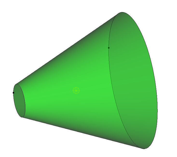
# Create first frustum/cone on the left side and subtract it from the main cylinder
create frustum height 1.5 radius 0.06 top 0.0569
# Move the frustum to its desired location
volume 2 move x -0.26
# Subtract frustum from cylinder
subtract volume 2 from volume 1
delete volume 2
# The result is still referred to as volume 1
# Create second smaller frustum/cone on top of the first on the left side
create frustum height 0.1 radius 0.0569 top 0.0139
# Move the frustum to its desired location
volume 3 move x -0.26 z 1.5
# Subtract this frustum from the main cylinder
subtract volume 3 from volume 1
delete volume 3
# The result is still referred to as volume 1
# Create third frustum/cone on the right side and subtract it from the main cylinder
create frustum height 1.55 radius 0.06 top 0.0569
# Move the frustum to its desired location
volume 4 move x 0.26
# Subtract frustum from cylinder
subtract volume 4 from volume 1
delete volume 4
# The result is still referred to as volume 1
# Create fourth smaller frustum/cone on top of the third on the right side
create frustum height 0.1 radius 0.0569 top 0.0139
# Move the frustum to its desired location
volume 5 move x 0.26 z 1.55
# Subtract this frustum from the main cylinder
subtract volume 5 from volume 1
delete volume 5
# The result is still referred to as volume 1
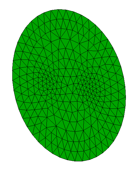
# Meshing with tetrahedra
mesh volume 1
Refine Tet all_of Volume 2 3 4 5 Size 0.025 Bias 1.5 Depth 2 Smooth
Thank you!