Hi, is this possible to refine the mesh around the YOZ plane without create a concrete wall during the meshing
reset
create cylinder height {12} radius {0.75}
volume 1 move z {12/2}
volume all scheme tetmesh
mesh volume all
Thanks!

Hi, is this possible to refine the mesh around the YOZ plane without create a concrete wall during the meshing
reset
create cylinder height {12} radius {0.75}
volume 1 move z {12/2}
volume all scheme tetmesh
mesh volume all
Thanks!
Hi,
you can select entitities with the extendet parsing syntax matching you criterias.
for example
draw tet all with x_coord > -1e-1 And x_coord < 1e-1
will draw you all tets in the given range, in this case near the yz plane.
the same approach also works for the refinement
refine tet all with x_coord > -1e-1 And x_coord < 1e-1 numsplit 1 bias 1.0 depth 1 smooth
Thanks, a follow up question, so I have small inlets in the cylinder, and they meshed with smaller grid so how to add yours to mine, now I am using this
# Define the scaling factor
#{u = 0.0254}

volume all size {0.09*u}
volume all scheme tetmesh
mesh volume all
i am not quite sure if i understand it right. do you want to refine over the whole cross section or just a part around the inlets?
could you please provide me a journal file or a picture
reset
graphics axis type origin on
# Define the scaling factor
#{u = 0.0254}

# Create main cylinder
create cylinder height {12.1*u} radius {0.75*u}
volume 1 move z {12.1/2 * u}

# Create cavity volumes
create frustum height {0.05*u} radius {0.06*u}   top {0.06*u}
create frustum height {1.45*u}  radius {0.06*u}   top {0.0569*u}
create frustum height {0.1*u}  radius {0.0569*u} top {0.0139*u}

create frustum height {0.05*u} radius {0.06*u}   top {0.06*u}
create frustum height {1.5*u} radius {0.06*u}   top {0.0569*u}
create frustum height {0.1*u}  radius {0.0569*u} top {0.0139*u}

#1
volume 2 move x {-0.26*u} z {(u*0.05/2)}
volume 3 move x {-0.26*u} z {(1.45/2 + 0.05)*u}
volume 4 move x {-0.26*u} z {(0.1/2 + 1.45 + 0.05)*u}

#2
volume 5 move x {0.26*u}  z {(u*0.05/2)}
volume 6 move x {0.26*u}  z {(1.5/2 + 0.05)*u}
volume 7 move x {0.26*u}  z {(0.1/2 + 1.5 + 0.05)*u}

# Subtract cavity volumes from main cylinder
subtract vol 2 3 4 5 6 7 from volume 1

# Compress entity id numbering
compress ids

# Create splitting surface

webcut volume 1 with plane zplane offset {1*(12/4)*0.0254}
merge volume 1 2

webcut volume 1 with plane zplane offset {2*(12/4)*0.0254}
merge volume 1 3

webcut volume 1 with plane zplane offset {3*(12/4)*0.0254}
merge volume 1 4

#webcut volume 1 with plane zplane offset {4*(12/4)*0.0254}
#merge volume 1 5

webcut volume 1 with plane zplane offset {12*0.0254}
merge volume 1 5


# Create mesh
volume all size {0.09*u}
volume all scheme tetmesh
mesh volume all

graphics mode transparent
#draw tet in tri in surface with is_merged
So I want the refine over YOZ, and inlets
With the above approach this would look like this
refine tet all with x_coord > {-0.09*u*0.4} And x_coord < {0.09*u*0.4} numsplit 1 bias 1.0 depth 1
refine surface 6 5 3 4 10 9 7 8 numsplit 1 bias 1.0 depth 1
volume all smooth scheme condition number beta 2.0 cpu 1
smooth volume all
It is not meshing on my side
i’ve run this on Coreform Cubit 2023.8 without any error
reset
graphics axis type origin on
# Define the scaling factor
#{u = 0.0254}

# Create main cylinder
create cylinder height {12.1*u} radius {0.75*u}
volume 1 move z {12.1/2 * u}

# Create cavity volumes
create frustum height {0.05*u} radius {0.06*u}   top {0.06*u}
create frustum height {1.45*u}  radius {0.06*u}   top {0.0569*u}
create frustum height {0.1*u}  radius {0.0569*u} top {0.0139*u}

create frustum height {0.05*u} radius {0.06*u}   top {0.06*u}
create frustum height {1.5*u} radius {0.06*u}   top {0.0569*u}
create frustum height {0.1*u}  radius {0.0569*u} top {0.0139*u}

#1
volume 2 move x {-0.26*u} z {(u*0.05/2)}
volume 3 move x {-0.26*u} z {(1.45/2 + 0.05)*u}
volume 4 move x {-0.26*u} z {(0.1/2 + 1.45 + 0.05)*u}

#2
volume 5 move x {0.26*u}  z {(u*0.05/2)}
volume 6 move x {0.26*u}  z {(1.5/2 + 0.05)*u}
volume 7 move x {0.26*u}  z {(0.1/2 + 1.5 + 0.05)*u}

# Subtract cavity volumes from main cylinder
subtract vol 2 3 4 5 6 7 from volume 1

# Compress entity id numbering
compress ids

# Create splitting surface

webcut volume 1 with plane zplane offset {1*(12/4)*0.0254}
merge volume 1 2

webcut volume 1 with plane zplane offset {2*(12/4)*0.0254}
merge volume 1 3

webcut volume 1 with plane zplane offset {3*(12/4)*0.0254}
merge volume 1 4

#webcut volume 1 with plane zplane offset {4*(12/4)*0.0254}
#merge volume 1 5

webcut volume 1 with plane zplane offset {12*0.0254}
merge volume 1 5


# Create mesh
volume all size {0.09*u}
volume all scheme tetmesh
mesh volume all

graphics mode transparent
#draw tet in tri in surface with is_merged

refine tet all with x_coord > {-0.09*u*0.4} And x_coord < {0.09*u*0.4} numsplit 1 bias 1.0 depth 1
refine surface 6 5 3 4 10 9 7 8 numsplit 1 bias 1.0 depth 1
volume all smooth scheme condition number beta 2.0 cpu 1
#smooth volume all
the smoothing at the last line is commented out.
which errors are you getting? what’s the version of cubit that you are using?
Thanks, a quick question, how to show the element numbers after refinement, now it only show before the refinement.
---------- Tet Refinement completed -----------

Finished Command: refine surface 6 5 3 4 10 9 7 8 numsplit 1 bias 1 depth 1

Cubit>volume all smooth scheme condition number beta 2.0 cpu 1

Finished Command: volume all smooth scheme condition number beta 2 cpu 1

Cubit>graphics mode transparent

Cubit>#draw tet in tri in surface with is_merged

Cubit>

Cubit>

Cubit>
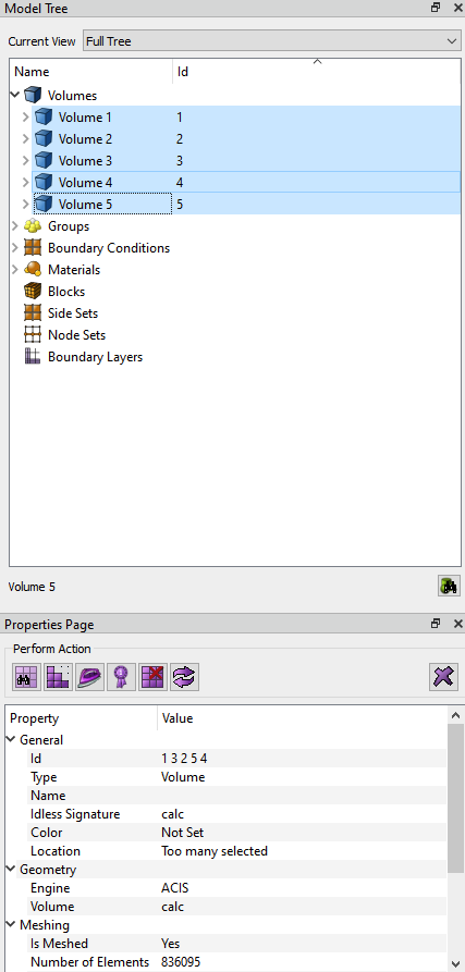
if you want to know the element count there are different ways to get this info.
a few examples:
you can select the volume in the model tree and look for it in the properties page
doing a mesh quality check will also tell you the element count
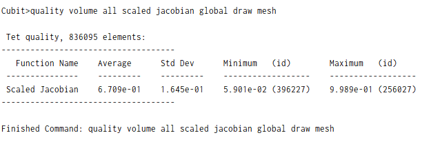
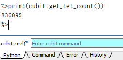
you can also use the python interface for this
print(cubit.get_tet_count())
will print out all the number of tet elements
Hi Norbert, @Norbert_Hofbauer I am trying to limit the number of while refining the YOZ and inlets. It is possible to make the YOZ and inlet super fine, and the rest grids are coarse so that the total grids number is below 400k.
Here is my script, so far the YOZ and inlet is not fine enough, IDK why there are some break in the refinement
reset
graphics axis type origin on
# Define the scaling factor
#{u = 0.0254}

# Create main cylinder
create cylinder height {12.1*u} radius {0.75*u}
volume 1 move z {12.1/2 * u}

# Create cavity volumes
create frustum height {0.05*u} radius {0.06*u}   top {0.06*u}
create frustum height {0.855*u}  radius {0.06*u}   top {0.0569*u}
create frustum height {0.025*u}  radius {0.0569*u} top {0.0139*u}

create frustum height {0.05*u} radius {0.06*u}   top {0.06*u}
create frustum height {0.875*u} radius {0.06*u}   top {0.0569*u}
create frustum height {0.025*u}  radius {0.0569*u} top {0.0139*u}

#1
volume 2 move x {-0.26*u} z {(u*0.05/2)}
volume 3 move x {-0.26*u} z {(0.855/2 + 0.05)*u}
volume 4 move x {-0.26*u} z {(0.025/2 + 0.855 + 0.05)*u}

#2
volume 5 move x {0.26*u}  z {(u*0.05/2)}
volume 6 move x {0.26*u}  z {(0.875/2 + 0.05)*u}
volume 7 move x {0.26*u}  z {(0.025/2 + 0.875 + 0.05)*u}

# Subtract cavity volumes from main cylinder
subtract vol 2 3 4 5 6 7 from volume 1

# Compress entity id numbering
compress ids

# Assign sets
nodeset 1 add surface 3 4 5
nodeset 1 name "B"

nodeset 2 add surface 7 8 9
nodeset 2 name "I"cap


nodeset 3 add surface 4
nodeset 3 name "P"

#block 1 add volume 1
#block 1 name 'core'


# Create splitting surface


webcut volume 1 with plane zplane offset {1*(12/4)*0.0254}
merge volume 1 2

webcut volume 1 with plane zplane offset {2*(12/4)*0.0254}
merge volume 1 3

webcut volume 1 with plane zplane offset {3*(12/4)*0.0254}
merge volume 1 4

webcut volume 1 with plane zplane offset {12*0.0254}
merge volume 1 5


# Create mesh
volume all size {0.3*u}
volume all scheme tetmesh
mesh volume all


graphics mode transparent

refine tet all with x_coord > {-0.09*u*0.4} And x_coord < {0.09*u*0.4} numsplit 2 bias 1.0 depth 1
refine surface 6 5 3 4 10 9 7 8 numsplit 1 bias 1.0 depth 1
volume all smooth scheme condition number beta 2.0 cpu 1


#draw tet in tri in surface with is_merged
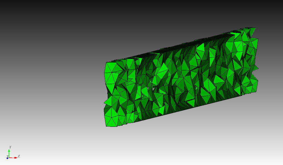
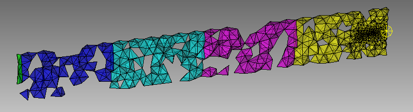
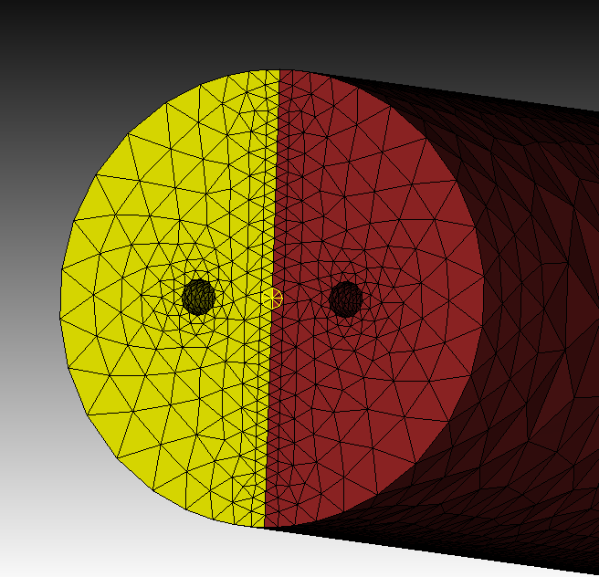
as you didn’t wanted to use a real surface for refinement we only catch tets that are in range for the refinement. drawing the tets right before refinement:
draw tet all with x_coord > {-0.09*u*0.4} And x_coord < {0.09*u*0.4}
so we end up with holes if the range isn’t wide enough.
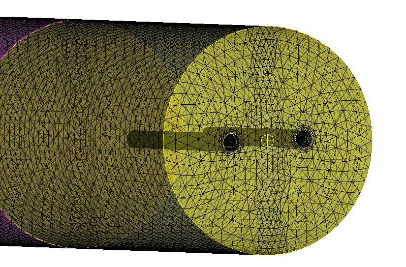
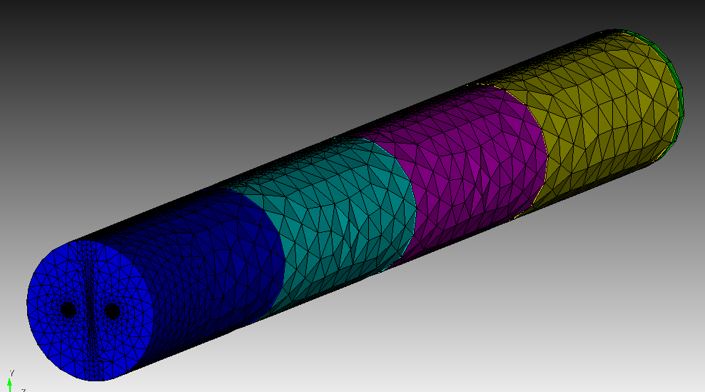
a cleaner approach would be to make a webcut in the yz plane and use the surfaces for refinement.
with adding the volumes to blocks, you still achieve your desired element sets on export.
reset
graphics axis type origin on
# Define the scaling factor
#{u = 0.0254}

# Create main cylinder
create cylinder height {12.1*u} radius {0.75*u}
volume 1 move z {12.1/2 * u}

# Create cavity volumes
create frustum height {0.05*u} radius {0.06*u}   top {0.06*u}
create frustum height {0.855*u}  radius {0.06*u}   top {0.0569*u}
create frustum height {0.025*u}  radius {0.0569*u} top {0.0139*u}

create frustum height {0.05*u} radius {0.06*u}   top {0.06*u}
create frustum height {0.875*u} radius {0.06*u}   top {0.0569*u}
create frustum height {0.025*u}  radius {0.0569*u} top {0.0139*u}

#1
volume 2 move x {-0.26*u} z {(u*0.05/2)}
volume 3 move x {-0.26*u} z {(0.855/2 + 0.05)*u}
volume 4 move x {-0.26*u} z {(0.025/2 + 0.855 + 0.05)*u}

#2
volume 5 move x {0.26*u}  z {(u*0.05/2)}
volume 6 move x {0.26*u}  z {(0.875/2 + 0.05)*u}
volume 7 move x {0.26*u}  z {(0.025/2 + 0.875 + 0.05)*u}

# Subtract cavity volumes from main cylinder
subtract vol 2 3 4 5 6 7 from volume 1

# Compress entity id numbering
compress ids

# Assign sets
nodeset 1 add surface 3 4 5
nodeset 1 name "B"

nodeset 2 add surface 7 8 9
nodeset 2 name "Icap"


nodeset 3 add surface 4
nodeset 3 name "P"

#block 1 add volume 1
#block 1 name 'core'


# Create splitting surface


webcut volume all with plane zplane offset {1*(12/4)*0.0254}
webcut volume all with plane zplane offset {2*(12/4)*0.0254}
webcut volume all with plane zplane offset {3*(12/4)*0.0254}
webcut volume all with plane zplane offset {12*0.0254}
webcut volume all with plane xplane

imprint vol all
merge vol all

# Create mesh
volume all size {0.3*u}
volume all scheme tetmesh
mesh volume all

block 1 add volume 1 6
block 2 add volume 5 10
block 3 add volume 4 9
block 4 add volume 3 8
block 5 add volume 2 7

graphics mode transparent

refine surface 6 5 3 4 10 9 7 8 numsplit 1 bias 1.0 depth 1

refine surface 28 60 52 44 36 numsplit 1 bias 1.0 depth 1
refine surface 28 60 52 44 36 numsplit 1 bias 1.0 depth 1
#volume all smooth scheme condition number beta 2.0 cpu 1

#draw tet in tri in surface with is_merged
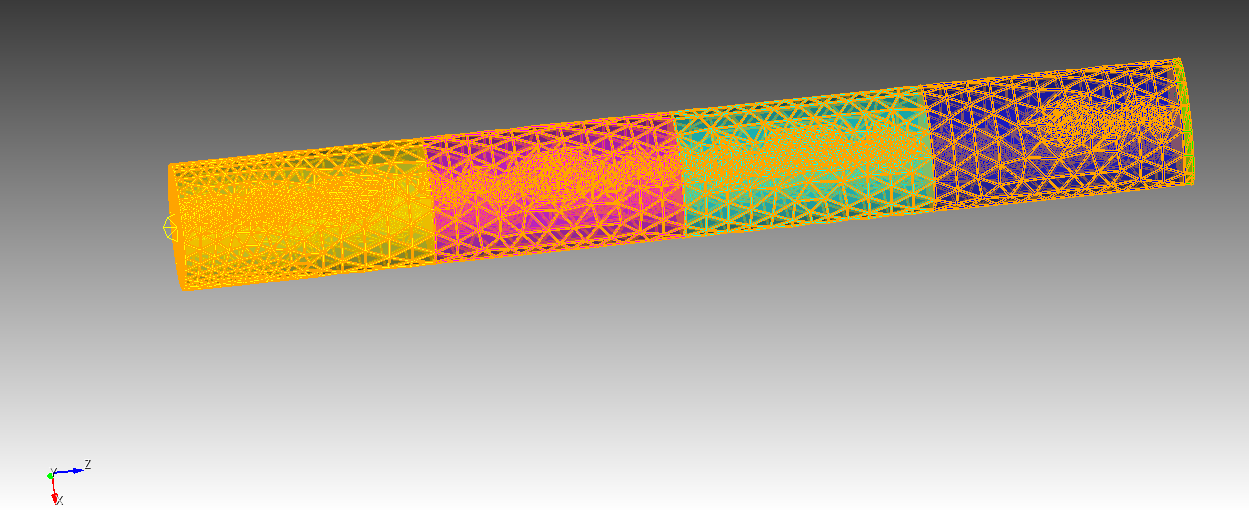
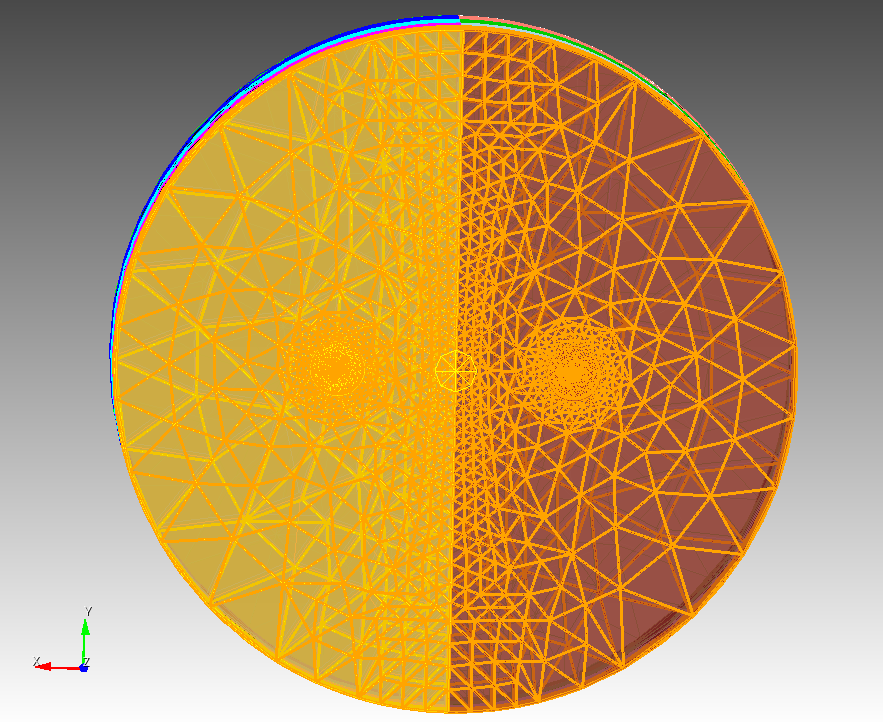
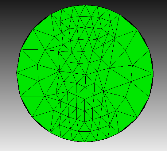
Thanks, @Norbert_Hofbauer , a follow-up question. Is there a way to make the refinement as same gird size along the Y axis, as you can see the part near the top (for example, y=5) and bottom (for example, y=-5) has bigger elements.
I tried to use a different numsplit, but it will over my cap element numbers.
you can try to refine by a target size
#refine surface 6 5 3 4 10 9 7 8 numsplit 1 bias 1.0 depth 1
#refine surface 28 60 52 44 36 numsplit 1 bias 1.0 depth 1
refine surface 6 5 3 4 10 9 7 8 size 0.001 bias 1.0 depth 1
refine surface 28 60 52 44 36 size 0.001 bias 1.0 depth 1
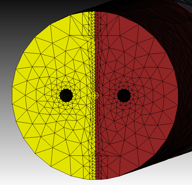
or mesh the surfaces with your wished size before meshing the volumes
reset
graphics axis type origin on
# Define the scaling factor
#{u = 0.0254}

# Create main cylinder
create cylinder height {12.1*u} radius {0.75*u}
volume 1 move z {12.1/2 * u}

# Create cavity volumes
create frustum height {0.05*u} radius {0.06*u}   top {0.06*u}
create frustum height {0.855*u}  radius {0.06*u}   top {0.0569*u}
create frustum height {0.025*u}  radius {0.0569*u} top {0.0139*u}

create frustum height {0.05*u} radius {0.06*u}   top {0.06*u}
create frustum height {0.875*u} radius {0.06*u}   top {0.0569*u}
create frustum height {0.025*u}  radius {0.0569*u} top {0.0139*u}

#1
volume 2 move x {-0.26*u} z {(u*0.05/2)}
volume 3 move x {-0.26*u} z {(0.855/2 + 0.05)*u}
volume 4 move x {-0.26*u} z {(0.025/2 + 0.855 + 0.05)*u}

#2
volume 5 move x {0.26*u}  z {(u*0.05/2)}
volume 6 move x {0.26*u}  z {(0.875/2 + 0.05)*u}
volume 7 move x {0.26*u}  z {(0.025/2 + 0.875 + 0.05)*u}

# Subtract cavity volumes from main cylinder
subtract vol 2 3 4 5 6 7 from volume 1

# Compress entity id numbering
compress ids

# Assign sets
nodeset 1 add surface 3 4 5
nodeset 1 name "B"

nodeset 2 add surface 7 8 9
nodeset 2 name "Icap"


nodeset 3 add surface 4
nodeset 3 name "P"

#block 1 add volume 1
#block 1 name 'core'


# Create splitting surface


webcut volume all with plane zplane offset {1*(12/4)*0.0254}
webcut volume all with plane zplane offset {2*(12/4)*0.0254}
webcut volume all with plane zplane offset {3*(12/4)*0.0254}
webcut volume all with plane zplane offset {12*0.0254}
webcut volume all with plane xplane

imprint vol all
merge vol all

# Create mesh
volume all size {0.3*u}
volume all scheme tetmesh

surface 6 5 3 4 10 9 7 8 size 0.001
surface 28 60 52 44 36 size 0.001
mesh surface 6 5 3 4 10 9 7 8
mesh surface 28 60 52 44 36

mesh volume all

block 1 add volume 1 6
block 2 add volume 5 10
block 3 add volume 4 9
block 4 add volume 3 8
block 5 add volume 2 7

graphics mode transparent

#refine surface 6 5 3 4 10 9 7 8 numsplit 1 bias 1.0 depth 1
#refine surface 28 60 52 44 36 numsplit 1 bias 1.0 depth 1
#refine surface 6 5 3 4 10 9 7 8 size 0.001 bias 1.0 depth 1
#refine surface 28 60 52 44 36 size 0.001 bias 1.0 depth 1
#volume all smooth scheme condition number beta 2.0 cpu 1

#draw tet in tri in surface with is_merged