Exodus sizing function from python netcdf4

Hello,

I am new to Cubit (and Exodus) and I would like to be able to add a mesh sizing function to a Cubit generated exodus file. I was previously using the background mesh strategy in Gmsh, but have decided to move on.

Using the netCDF4 Python module, I am able to convert the file to a format I can use in my simulator. I would now like to add a sizing function back into the original exodus file.

According to this documentation, this needs to be a time-based (element or nodal) variable:
https://coreform.com/cubit_help/mesh_generation/adaptivity_and_sizing_functions/exodus2_field_function.htm

Are there any available examples for doing this? If I do a nodal array, does it just need to be the same dimension as the coordinates of the whole structure? If I do an element array, does it need to be the size of the block, or the total size of all the elements?

Regards,

Juan

This is what I have been able to come up with so far, but I have no insight if this format will be close to correct.
timedata.py (488 Bytes)

Welcome @js34654!

You can find comprehensive Exodus documentation on Sandia’s open-source repository for their SEACAS project, which owns the Exodus format. (SEACAS stands for: "Sandia Engineering Analysis Code Access System)

If you have access to Linux or Mac, you can build the SEACAS project, which will give you access to a few useful utilities utilities to convert Exodus to & from ASCII text (exotxt / txtexo), and to/from Matlab *.mat files ( exo2mat / mat2exo ). There are also extensive APIs for C, Fortran, and Python ( exodus.py ). You may find these tools useful for understanding & creating your Exodus file.

Of course, you could also use the meshio Python module to convert into Exodus from a format that’s more familiar to you.

I’ve attached two files to this email to help get you started with Exodus:

And here’s a script that will operate on those files to do sizing. Note that Cubit computes mesh size range by scaling the variable range to the min_size - max_size in the sizing command - small values result in smaller elements. This may seem counter-intuitive if you’ve used a stress variable as your sizing function as high positive values result in larger elements, while small numbers (large negative values if they exist) will correspond to the smallest elements. So I would recommend creating a custom scalar variable where you compute the sizing function.

reset
import step "/path/to/ASTM_E8-Round-1.step" heal
webcut volume all  with loop curve 1  
webcut volume all with loop curve 1  
webcut volume all with loop curve 4  
webcut volume all with loop curve 7  
webcut volume all  with loop curve 3  

imprint all
merge all

## Use Element Variable (Von Mises Stress) as sizing Function
#import sizing function "/path/to/params_out.e" block 1 variable "von_mises" time 1

## Use Nodal Variable (Z-Displacement) as sizing Function
import sizing function "/path/to/params_out.e" block 1 variable "disp_z" time 1

volume all sizing function type exodus min_size 1 max_size 10
mesh volume all

Sizing by Von Mises Stress


Sizing by Z-Displacement


Thanks for the files and links to the site. I am hoping the ncdump of params_out.e has all of the info I need. It looks like I just need to follow this format:

double vals_nod_var1(time_step, num_nodes) ;
double vals_nod_var2(time_step, num_nodes) ;
double vals_nod_var3(time_step, num_nodes) ;
char name_nod_var(num_nod_var, len_name) ;

and put the names in the name_node_var array and the values into the vals_nod_var*. And expand:

time_whole = 0, 1 ;

I was able to write a script to update a sizing variable, mytestvar, to the values of coordx.
test.py (558 Bytes)

@gvernon Thanks again for your help reverse engineering the format.

I am memorializing the numbering of the element sides here:
https://gsjaardema.github.io/seacas-docs/html/element_types.html#tet

if I need to do any sideset conversions for new elements.

@gvernon are the sizing function values the distance between nodes (edge length), or some other calculation?

Yes, it should be approximately the edge length. Recall, however, that the values are mapped to the range of (min_size, max_size) in the command.

Thanks for your response. So the appropriate strategy would be for me to put the desired node sizes in the time dependent variable, and not specify min_size and max_size on the sizing function statement? Is setting a growth factor in conjunction with the sizing function available?

Essentially, the time-dependent variable will store the relative sizes of the elements. Let’s say you have a 4-element 1-D mesh with the values of the sizing variable:

s = [42, 50, 88, 130]

and using the command

volume all sizing function type exodus min_size 1 max_size 10

Then the resulting element sizes would be:

element_size = [1, 1.8, 5.7, 10]

However, this may not be attainable if the geometry doesn’t permit this sizing (e.g. if the entire length of the curve is only 3 units). But this is my understanding of what the sizing function is trying to do.

So when I reload my .cub5 with my initial mesh, and try to remesh from the command line, it doesn’t seem to work. When I try it from the gui, it asks me about deleting the existing mesh and proceeding. Do I need to somehow delete the initial mesh before trying the sizing function?

Hello,

I’m currently trying to run this example (using Von Mises Stress) and it does not appear to be working correctly. When I attempt to mesh the volume, I get an error of “invalid syntax in parse_cubit_list” and the resulting mesh is uniform:

I’m running this in Cubit 2025.1. I’m not sure if this is potentially causing an issue. I’ve included the journal file and the cubit file for the meshed geometry below. Please let me know if I can do anything else to help resolve this.

cubit81.jou (1.2 KB)
ASTM_test.cub5 (2.8 MB)

Thank you,

Sam Elkin

Hi Sam, welcome to the forum!

Nevermind my original message, didn’t realize this wasn’t a new thread… are you using the above-attached params.out file or did you create a new file on your system using MOOSE?

@selkin – Took a quick look at this, assuming you’re using the attached params.out file I believe your issue is just syntax related. You’re using step 1 however, Coreform Cubit uses 1-based indexing for Exodus step ids. Since step 1 is the initial step of your simulation, all the values are zero (i.e., uniform). If you use either:

import sizing function "params_out.e" block 1 variable "von_mises" step 2

or

import sizing function "params_out.e" block 1 variable "von_mises" last

It should work for you – let me know if it doesn’t.


Also, FWIW, the 1-based indexing is the definition within the Exodus format definition:

Hi Greg, thanks for responding, and sorry for the delay in getting back to you! I was using the provided params.out file, and the fix you provided did resolve the problem. Thank you again for your help!

However, I’m still having some trouble using the exodus sizing function for my own application. I’m trying to use this functionality to perform an adaptive mesh refinement procedure, where I generate an initial mesh, run my code, estimate the error in my solution, and write the error back into the exodus file to generate a new mesh. While a new mesh gets created, it appears to be uniform, similar to the issue I was having above. The parse_cubit_list error I was seeing previously also occurs, although I’m not sure how relevant that is.

I’ve included the cubit file for the geometry, the exodus file containing the original mesh (which is the same as that of the cubit file, and is generated using an approximate size of 0.003) and the sizing function, and a journal file showing my current procedure. Please let me know if you have an idea of what I’m doing incorrectly.

microstrip_coarse.cub5 (433.1 KB)
microstrip_coarse.e (182.5 KB)
cubit87.jou (881 Bytes)

Thanks again,

Sam Elkin

There’s maybe a few things happening here.


The variable testVar that you’re using for the scaling appears to be an element-variable. From the documentation:

If an element-based variable is used for the sizing function each node is assigned a value that is the average of variables on all connected elements. Nodal variables are used directly.

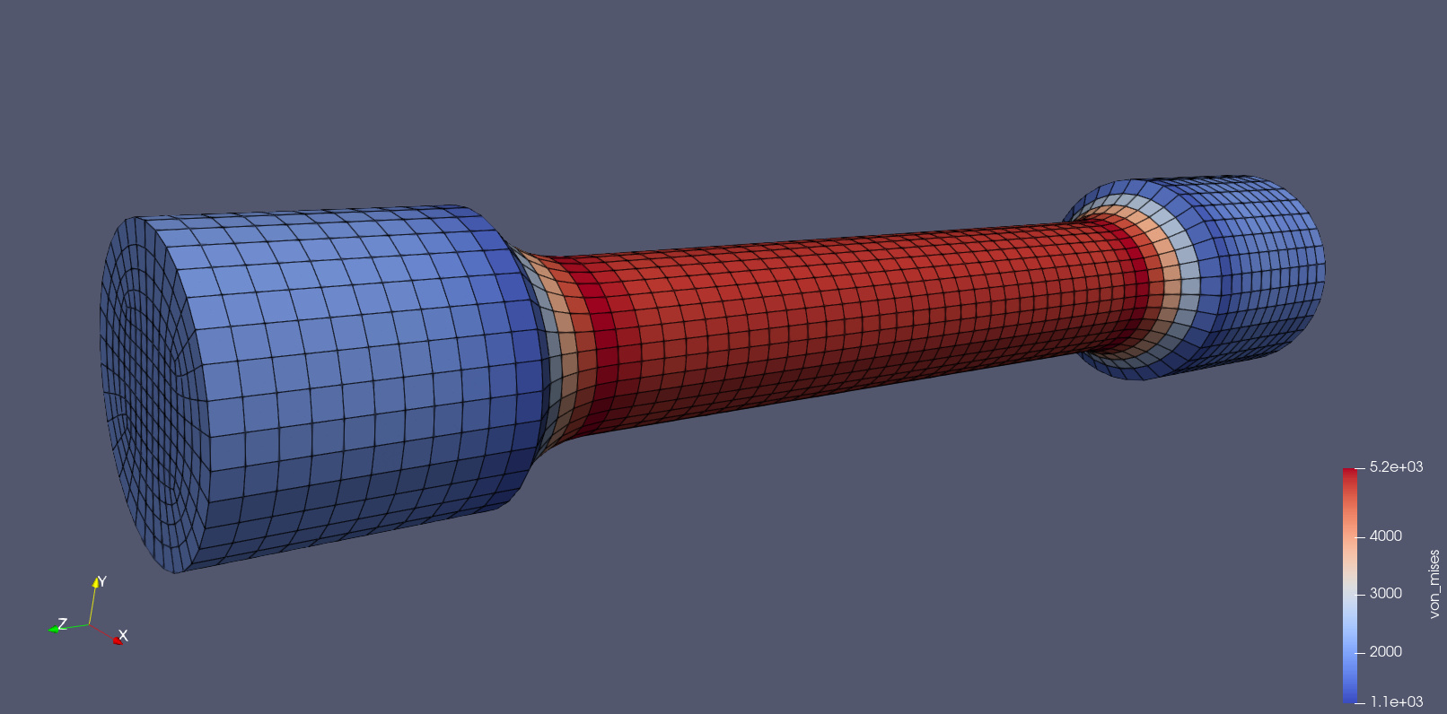
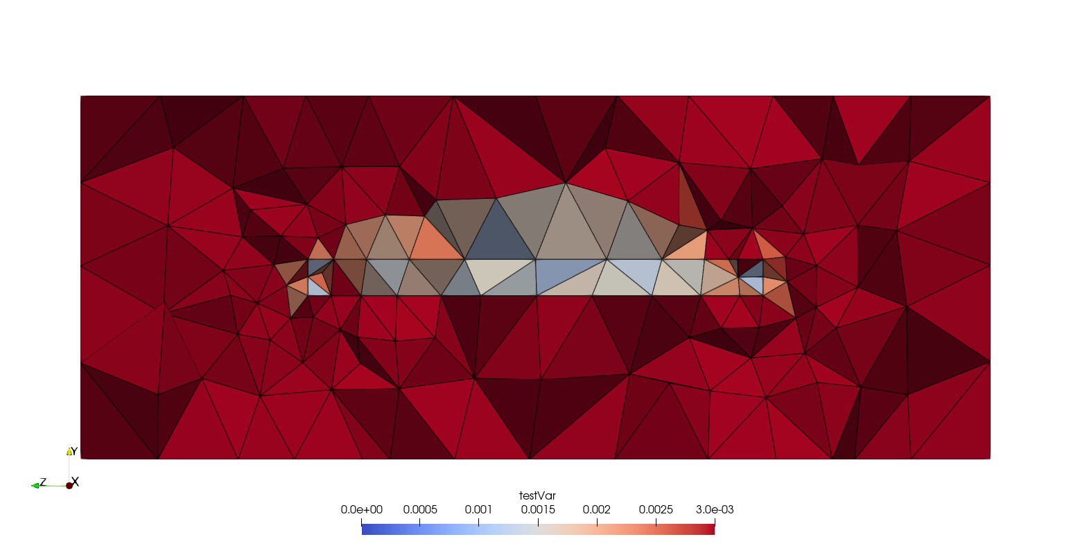
Looking at the exodus file in ParaView, with a clip filter applied, my guess is that the averaging step is “rounding up” a lot of the values.

I used the CellDataToPointData filter as a poor-mans approach to getting nodal variables instead, and then did Save Data to a new exodus file.

Note that if you use the ParaView-generated exodus file, the blocks get renumbered (for me anyways) to blocks 10 and 92 for some unknown reason… the best thing for you to do is to request your solver to output the element data as nodal data. I assume you’re using MOOSE? If so, I believe you’ll want to use ProjectionAux to do this.


Also, note that the actual data-range of the tet-meshed blocks is [0.0008263886326796536, 0.003]. However, since you used block all in the import sizing function command it will grab the min/max values across all blocks, which is [0, 0.003]. What this means is that, when you define the min_size value in the sizing function exodus command, that a value of 0.0 will map to the size value of 0.0008, while the minimum value within the tet-meshed block regions will map to a value of 0.0014 – making your effective sizing range: [0.0014, 0.003]. Instead you’ll want to use block 1 2 (or block 10 92 if using the ParaView approach).


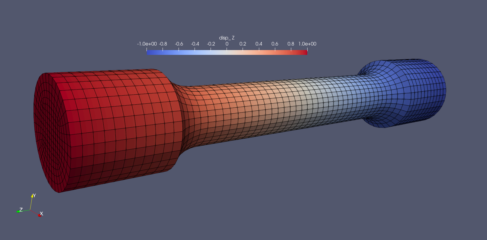
With the above two changes (using ParaView approach) I now have:

reset

open "microstrip_coarse.cub5"
reset vol all

vol all scheme tetmesh

import sizing function "microstrip_coarse_nodal.e" block 10 92 variable "testVar" step 2
volume 1 2 sizing function exodus min_size 0.0008 max_size 0.003
mesh vol 1 2

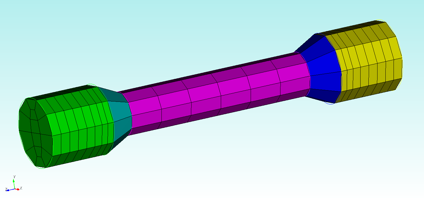
Which still results in a pretty-coarse mesh:

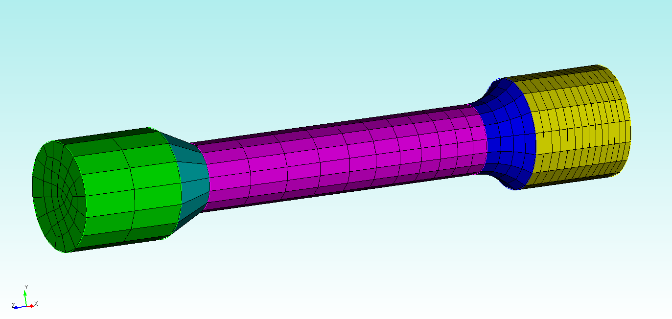
This is likely due to the relatively large region that will have a large mesh size (0.003) and the relatively small region that has a mesh size that is still ~1/3 the size of the coarse mesh. Arguably, this is exactly what you asked for as the element lengths on the top of the yellow are ~0.003 and in the green volume are ~0.001. If you want a starker contrast, try decreasing the min_size to {0.0008/10}:

And if you want the mesh to be finer than that, you could either decrease the the min_size and max_size together, here’s [{0.0008/10}, {0.003/10}]):

Or by using the optional argument Scale_Mesh_Multiplier <value>. Here are two examples:

volume 1 2 sizing function exodus min_size {0.0008/1} max_size {0.003/1} Scale_Mesh_Multiplier 10

volume 1 2 sizing function exodus min_size {0.0008/10} max_size {0.003/1} Scale_Mesh_Multiplier 10


I’m partial to the final mesh, so here’s the script (again, using the ParaView-generated exodus file):

reset

open "microstrip_coarse.cub5"
reset vol all

vol all scheme tetmesh

import sizing function "microstrip_coarse_nodal.e" block 10 92 variable "testVar" step 2
volume 1 2 sizing function exodus min_size {0.0008/10} max_size {0.003/1} Scale_Mesh_Multiplier 10
mesh vol 1 2 

Thank you for the detailed writeup, this is incredibly helpful!

On the averaging point, I’m not sure I’m following your argument. From looking at the documentation for cellDataToPointData (VTK: vtkCellDataToPointData Class Reference), it seems like the same sort of averaging is being performed in ParaView:

The data is coming from a custom FEM code, so I can add a function to perform this functionality directly if need be, but I’m not sure if it’s necessary at this point. Is the averaging procedure in Cubit any differently than that of ParaView (at least at a high level)?

You’re welcome!

I wasn’t sure how ParaView did it, it does appear to be (high-level) the same approach. At the very-least it allowed me to see the actual mapping being used by Cubit to do the sizing function.