Hello,
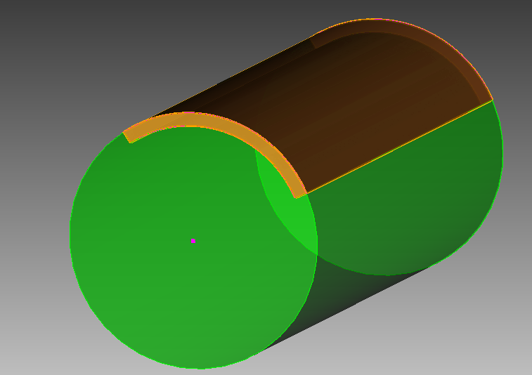
I’m trying to create a cylinder with two volumes: one that is a relatively thin shell but only for a specified arc length at the surface of the cylinder and some distance within it and the other volume being the remainder of the cylinder. To give you an idea of what I’m going for here is a top view of what I would like to accomplish:

As an example, let’s try this with a cylinder of height 10 and radius 2 with an arc shell of a total of 100 degrees and thickness 0.2
My approach so far involves creating a cylinder, making new vertices based upon the one defining one of the cylinder’s circular surfaces, then using those to define the outer arc curve:
create cylinder height 10 radius 2
create vertex on curve 2 fraction 0.388888889
create vertex on curve 2 fraction 0.25
create vertex on curve 2 fraction 0.1111111111
create curve arc three vertex 5 4 3
So now I have Curve 3, a free curve which I believe I should then copy and transform into a curve of the same arc angles but radius of 1.8 to then use to define a surface which I can then sweep through the length of the cylinder to then copy and use one of these volumes to remove that material from the original cylinder volume. I try to copy and transform the copy, but I can’t seem to find the curve after the transformation operation, so I don’t know if it is doing what I need it to do… What should I do to replicate the geometry regions in the attached picture?
Some questions: Is this the approach you would take? Is there a more efficient way to accomplish what I want to do? Am I even thinking of this correctly?
Any help would be greatly appreciated!
Hi @jbtompkins - I’ll address your question shortly, in the meantime I just wanted to let you know I edited your post to fix formatting of the code-block.
By using three ` characters you can create a code-block:
```
create cylinder height 10 radius 2
create vertex on curve 2 fraction 0.388888889
create vertex on curve 2 fraction 0.25
create vertex on curve 2 fraction 0.1111111111
create curve arc three vertex 5 4 3
```
results in:
create cylinder height 10 radius 2
create vertex on curve 2 fraction 0.388888889
create vertex on curve 2 fraction 0.25
create vertex on curve 2 fraction 0.1111111111
create curve arc three vertex 5 4 3
Yes, I saw this. Thank you for editing the formatting for clarity!
OK, so I believe I’ve figured this out. Instead of using the three vertex arc curve creation command as I was doing, the center angle defined arc command is easier to use for what I need:
create Cylinder height 10 radius 2
create vertex center curve 2
create curve arc radius 2 center location at vertex 3  normal 0 0 1  start angle 40 stop angle 140
create curve arc radius 1.8 center location at vertex 3  normal 0 0 1  start angle 40 stop angle 140
So now that I have two curves defining the arcs that I want and all the vertices I need, I just need two more curves to define a surface using these four curves as bounding curves:
create curve vertex 4 6
create curve vertex 5 7
create surface curve 3 4 5 6 on surface 3
Now I just sweep the resulting surface and remove the overlap from the larger component
sweep surface 4 perpendicular distance 10 switchside 10  keep
remove overlap volume 3 1 modify larger
And I think I’m done!
Anyways, please let me know if you believe there is a better way to do this or an efficient method to mesh this such that nodes between the two volumes are consistent.
Thanks!
@jbtompkins - There is a slightly simpler way (in my opinion):
reset

## Create Base Cylinder
cylinder height 10 radius 2

## Construct Hollow Cylinder
cylinder height 10 radius 2
cylinder height 10 radius 1.8
subtract vol 3 from vol 2

## Chop Hollow Cylinder to specified arc-length
webcut volume 2 with plane xplane rotate 50 about z
webcut volume 2 with plane xplane rotate 140 about z
delete vol 4 5

## Remove overlapping portion from base cylinder
remove overlap volume 1 2 modify larger
I’ve also taken the liberty to put this into Cubit-Python, which could help with automation down the road:
def create_modified_cylinder(height, radius, thickness, angle):
  ## Get last created ids in current model
  last_vol_id, last_surf_id, last_curve_id, last_vertex_id = get_last_ids()
  ## Create base cylinder
  cubit.cmd('create Cylinder height {} radius {}'.format(height, radius))
  ## Create thin section
  cubit.cmd('create Cylinder height {} radius {}'.format(height, radius))
  cubit.cmd('create Cylinder height {} radius {}'.format(height, radius-thickness))
  cubit.cmd("subtract vol {} from vol {}".format(last_vol_id+3, last_vol_id+2))
  cubit.cmd("webcut volume {} with plane xplane rotate {} about z".format(last_vol_id+2, 90-angle/2))
  cubit.cmd("webcut volume {} with plane xplane rotate {} about z".format(last_vol_id+2, 90+angle/2))
  cubit.cmd("delete vol {} {}".format(last_vol_id+4, last_vol_id+5))
  cubit.cmd("remove overlap volume {} {} modify larger".format(last_vol_id+1, last_vol_id+2))

def get_last_ids():
  last_vol_id = cubit.get_last_id("volume")
  last_surf_id = cubit.get_last_id("surface")
  last_curve_id = cubit.get_last_id("curve")
  last_vertex_id = cubit.get_last_id("vertex")
  return last_vol_id, last_surf_id, last_curve_id, last_vertex_id
You would run this by executing the function:
create_modified_cylinder(10, 2, 0.2, 100)
or however you wish to pass values into the function. The value of this approach is that it works regardless of how many other objects are in your model. You could have an entire 747 loaded into Coreform Cubit, and you could add one of these modified cylinders without worrying about ids!
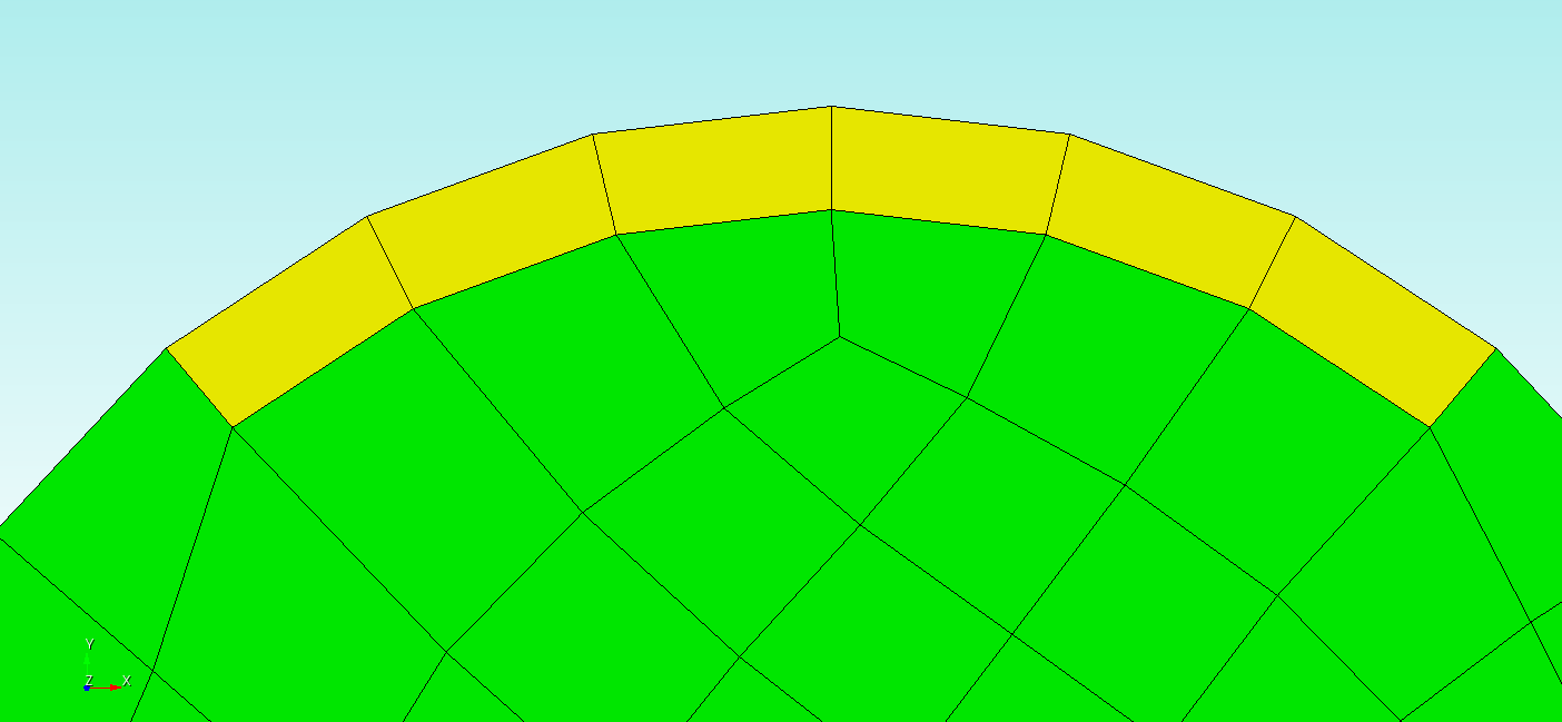
If you’re wondering how to ensure “consistent nodes” – which I presume you mean that you want a conforming mesh – then you’ll need to imprint and merge the volumes:
imprint volume 1 2
merge volume 1 2
prior to meshing. Essentially, imprinting and merging is how you communicate that two neighboring geometric entities are connected.
Without Imprint and Merge
With Imprint and merge
1 Like