Cubit Meshing Error: Volume 5 Requires Explicit Meshing Scheme (Not Automatically Mappable/Submappable/Sweepable)

Problem Description

When executing the mesh volume all command to generate volume meshes, Volume 3 meshed successfully (automatically using the submap scheme, generating 160820 hex elements), but Volume 5 failed with an error.

Error Details

WARNING: Volume 5 must have its meshing scheme explicitly specified; 
it is not automatically mappable, submappable or sweepable.  
ERROR: 1 volume did not mesh : Volume 5  

The original code is as follows:

#!/usr/bin/env python

from __future__ import print_function
import cubit
cubit.init([""])
try:
	from geocubitlib import boundary_definition
	from geocubitlib import cubit2specfem3d
except:
	import boundary_definition
	import cubit2specfem3d

import os
import sys
cubit.cmd('reset')


# --------------------  -------------------- #
# cubit.cmd('view journal')   
cubit.cmd('Timer Start')                        
cubit.cmd('clear')                              
cubit.cmd('Color Background white')             
cubit.cmd('Color Axis Labels red')              

cubit.cmd('graphics perspective off')
cubit.cmd('graphics parallel scale  303.79899')
cubit.cmd('from -2209.0335 -2399.8038  840.56353')
cubit.cmd('at            0          0          0')
cubit.cmd('up    0.15018128  0.20082845  0.96804624')

cubit.cmd('set duplicate block elements on')    

# cubit.cmd('view right')    
# cubit.cmd('up 0 0 1')                           

# cubit.cmd('view top')    

# cubit.cmd('view bottom') 

# cubit.cmd('view front') 

cubit.cmd('view iso')
cubit.cmd('up 0 0 1') 
# --------------------  -------------------- # 


# --------------------  -------------------- #
elementsize = 4.0
path_folder = 'model_files_3D_20250803'
# --------------------  -------------------- #


# ----------------------------------------  ---------------------------------------- #
cubit.cmd('brick 	  x 200 y 200 z  200')

cubit.cmd('move vol 1 x 100 y 100 z -100')

cubit.cmd('create sphere radius 3 Zpositive')

cubit.cmd('move volume 2 x 100 y 100 z -150')
# ----------------------------------------  ---------------------------------------- #


cubit.cmd('view iso')
cubit.cmd('up 0 0 1') 


# --------------------  -------------------- #
cubit.cmd('color vol 1  id 4')		
cubit.cmd('color vol 2  id 10')		
# --------------------  -------------------- #


# --------------------  -------------------- #
cubit.cmd('imprint vol all')

cubit.cmd('volume all size ' + str(elementsize))

cubit.cmd('mesh volume all')
cubit.cmd('draw volume all')

Hi @Hang_Duan,
could you share the model that you create with specfem as a .cub5 ?

Hi @Norbert_Hofbauer,
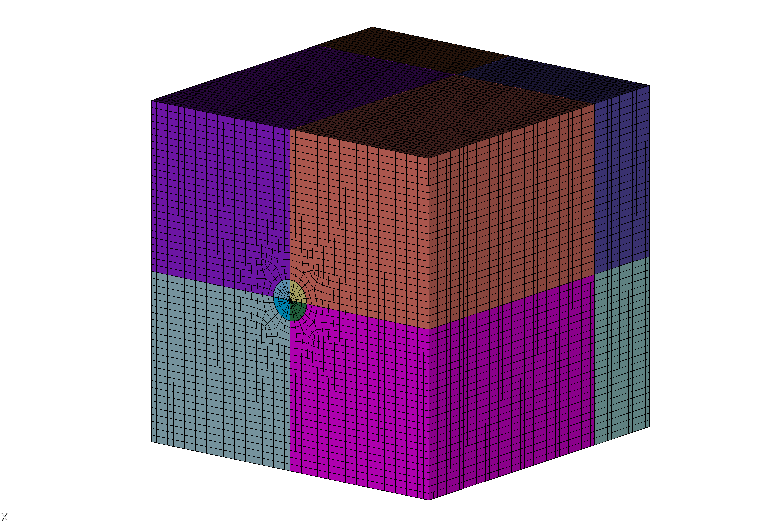
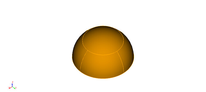
I am not certain if I have correctly grasped the meaning of your statement. In the problem I raised, my intention is to create a cubic domain measuring 200 m × 200 m × 200 m, within which an upper hemisphere with a radius of 30 m is embedded; the lower base of this hemisphere is situated at a depth of 150 m inside the cube. I aim to discretize this model using an unstructured mesh with a predefined element size of 4 m × 4 m × 4 m. However, an error occurred when executing the command cubit.cmd(‘mesh volume all’), which consequently prevented the generation of any model files.

Although SPECFEM3D can indeed generate model files, this capability is limited to regular models and does not apply to irregular models such as the one I described. I used SPECFEM3D to generate a model with dimensions of 120 m × 120 m × 120 m, discretizing it with a mesh of 4 m × 4 m × 4 m element size. The generated model files are in the .bin and .vtk formats, rather than the .cub5 format.

My understanding of the operations for creating models using CUBIT software is very limited, and I still remain unsure about how to resolve the problem I previously raised at this moment.

Hi @Hang_Duan,

I think there is a misunderstanding here. Typically, spectral analysis codes such as SPECFEM3D require a hexahedral mesh. You need to do some additional steps to create valid Coreform Cubit geometry and decompose those volumes to get a good hex mesh. The imprint and merge steps are used after decomposing the geometry to ensure that the model is contiguous. Here is a journal file that creates a valid hex mesh for your part.

#!cubit
reset

# Create and position the initial geometry
brick x 200 y 200 z 200
move volume 1 x 100 y 100 z -100
create sphere radius 3 Zpositive
move volume 2 x 100 y 100 z -150
subtract volume 2 from 1 keep_tool

# set up some names to help later
volume 2 name "hemi"
volume 3 name "outer"

# Perform the final webcuts to partition the model
webcut volume all with cylinder radius 1 axis z center 100 100 -150
volume with name "outer@*" name "cyl_cut"
volume with name "hemi@*" name "cyl_cut"
webcut volume all except with name "cyl_cut*" with plane xplane offset 100
webcut volume all except with name "cyl_cut*" with plane yplane offset 100
webcut volume all with plane zplane offset -150
webcut volume all with cylinder radius 12 axis z center 100 100 -150
webcut volume 23 to 26 with plane zplane offset -132

# Imprint and merge to prepare for meshing
imprint all
merge all

# Set the global and local meshing schemes and sizes
volume all size 4.0

# Get more refined size around the hemisphere
curve with radius <  3 interval 6
# force the surface meshing scheme on some surfaces so Cubit can mesh the volumes
surface with z_coord < -199 scheme pave
surface with area < 113 with area > 112 scheme map
# Generate the final mesh
mesh volume all

Karl

Hi @kgmerkley,
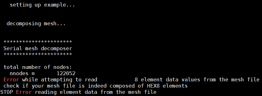
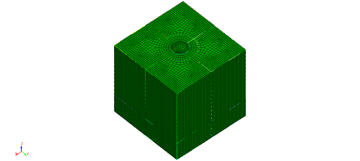
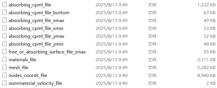
Thank you for your assistance. Inspired by the code you provided, I successfully implemented the mesh generation for a model featuring a cube containing an upper hemisphere. However, as you noted, the SPECFEM3D code requires 8-node hexahedral (HEX8) meshes as input. Using the following Python script, I generated 11 model files and used them as inputs for SPECFEM3D. During execution, an error occurred: “Error while attempting to read 8 element data values from the mesh file” , indicating that the mesh file does not contain HEX8 elements. In this situation, how can I ensure that the output mesh consists of 8-node hexahedral elements?

My Python code is as follows:
#!/usr/bin/env python

from future import print_function

import cubit

cubit.init([""])

try:

from geocubitlib import boundary_definition

from geocubitlib import cubit2specfem3d

except:

import boundary_definition

import cubit2specfem3d

import os

import sys

cubit.cmd(‘reset’)

cubit.cmd(‘Timer Start’)

cubit.cmd(‘clear’)

cubit.cmd(‘Color Background white’)

cubit.cmd(‘Color Axis Labels red’)

cubit.cmd(‘graphics perspective off’)

cubit.cmd(‘graphics parallel scale 303.79899’)

cubit.cmd(‘from -2209.0335 -2399.8038 840.56353’)

cubit.cmd(‘at 0 0 0’)

cubit.cmd(‘up 0.15018128 0.20082845 0.96804624’)

cubit.cmd(‘set duplicate block elements on’)

cubit.cmd(‘view iso’)

cubit.cmd(‘up 0 0 1’)

elementsize = 4.0

path_folder = ‘model_files_3D_20250812’

cubit.cmd(‘brick x 200 y 200 z 200’)

cubit.cmd(‘move vol 1 x 100 y 100 z -100’)

cubit.cmd(‘create sphere radius 30 Zpositive’)

cubit.cmd(‘move volume 2 x 100 y 100 z -150’)

cubit.cmd(‘subtract volume 2 from 1 keep_tool’)

cubit.cmd(‘volume 2 name “hemi”’)

cubit.cmd(‘volume 3 name “outer”’)

cubit.cmd(‘webcut volume all with cylinder radius 20 axis z center 100 100 -150’)

cubit.cmd(‘volume with name “outer@*” name “cyl_cut”’)

cubit.cmd(‘volume with name “hemi@*” name “cyl_cut”’)

cubit.cmd(‘webcut volume all except with name “cyl_cut*” with plane xplane offset 100’)

cubit.cmd(‘webcut volume all except with name “cyl_cut*” with plane yplane offset 100’)

cubit.cmd(‘webcut volume all with plane zplane offset -150’)

cubit.cmd(‘webcut volume all with cylinder radius 40 axis z center 100 100 -150’)

cubit.cmd(‘webcut volume 21 to 24 with plane zplane offset -132’)

cubit.cmd(‘color volume with name “hemi*” blue’)

cubit.cmd(‘color volume with name “outer*” id 4’)

cubit.cmd(‘draw volume all’)

cubit.cmd(‘imprint all’)

cubit.cmd(‘merge all’)

cubit.cmd('volume all size ’ + str(elementsize))

cubit.cmd(‘curve with radius < 4 interval 6’)

cubit.cmd(‘surface with z_coord < -199 scheme pave’)

cubit.cmd(‘surface with area < 100 with area > 20 scheme map’)

cubit.cmd(‘mesh volume all’)

cubit.cmd(‘Geometry visibility ON’)

cubit.cmd(‘Mesh visibility ON’)

cubit.cmd(‘Surface 25 144 151 154 162 164 172 174 182 Name “Zmax”’)

cubit.cmd(‘Surface 26 185 192 195 202 207 209 215 222 Name “Zmin”’)

cubit.cmd(‘Surface 108 115 129 130 Name “Xmax”’)

cubit.cmd(‘Surface 117 123 136 142 Name “Xmin”’)

cubit.cmd(‘Surface 126 133 135 141 Name “Ymax”’)

cubit.cmd(‘Surface 111 112 118 124 Name “Ymin”’)

cubit.cmd(‘block 1001 face in surface with name “Zmax@*”’)

cubit.cmd(‘block 1001 name “face_topo”’)

cubit.cmd(‘block 1002 face in surface with name “Zmin@*”’)

cubit.cmd(‘block 1002 name “face_bottom”’)

cubit.cmd(‘block 1003 face in surface with name “Xmin@*”’)

cubit.cmd(‘block 1003 name “face_abs_xmin”’)

cubit.cmd(‘block 1004 face in surface with name “Ymin@*”’)

cubit.cmd(‘block 1004 name “face_abs_ymin”’)

cubit.cmd(‘block 1005 face in surface with name “Xmax@*”’)

cubit.cmd(‘block 1005 name “face_abs_xmax”’)

cubit.cmd(‘block 1006 face in surface with name “Ymax@*”’)

cubit.cmd(‘block 1006 name “face_abs_ymax”’)

cubit.cmd(‘block 1 hex in volume with name “hemi@*”’)

cubit.cmd('block 1 name "elastic 1 " ') # material region

cubit.cmd(‘block 1 attribute count 7’)

cubit.cmd('block 1 attribute index 1 1 ') # volume 2

cubit.cmd('block 1 attribute index 2 3800 ') # vp

cubit.cmd('block 1 attribute index 3 2220 ')# vs

cubit.cmd('block 1 attribute index 4 2250 ') # rho

cubit.cmd('block 1 attribute index 5 9999.0 ')# Qkappa

cubit.cmd('block 1 attribute index 6 9999.0 ')# Qmu

cubit.cmd('block 1 attribute index 7 0 ') # anisotropy_flag

cubit.cmd(‘block 2 hex in volume with name “outer@*”’)

cubit.cmd('block 2 name “elastic 2” ') # material region

cubit.cmd(‘block 2 attribute count 7’)

cubit.cmd('block 2 attribute index 1 2 ') # volume 2

cubit.cmd('block 2 attribute index 2 4000 ') # vp

cubit.cmd('block 2 attribute index 3 2350 ')# vs

cubit.cmd('block 2 attribute index 4 2300 ') # rho

cubit.cmd('block 2 attribute index 5 9999.0 ')# Qkappa

cubit.cmd('block 2 attribute index 6 9999.0 ')# Qmu

cubit.cmd('block 2 attribute index 7 0 ') # anisotropy_flag

from geocubitlib import boundary_definition

from geocubitlib import cubit2specfem3d

os.system('mkdir ’ + path_folder)

cubit.cmd(‘export mesh "’ + path_folder + ‘/top.e" dimension 3 overwrite’)

cubit.cmd(‘save as "’ + path_folder + ‘/meshing.cub" overwrite’)

cubit.cmd(‘save as "’ + path_folder + ‘/top.cub" overwrite’)

cubit2specfem3d.export2SPECFEM3D(path_folder, cpml = True, cpml_size = 20, top_absorbing = False)
Hi @Han_Duan,

Be careful with the definition of block and sideset in Cubit. All of your blocks (material regions) should be on volumes on or on hex in volume. When you do

cubit.cmd(‘block 1001 face in surface with name “Zmax@*”’)
cubit.cmd(‘block 1001 name “face_topo”’)
cubit.cmd(‘block 1002 face in surface with name “Zmin@*”’)
cubit.cmd(‘block 1002 name “face_bottom”’)

You are creating element groups of faces that will be SHELL4 by default. If you want to create these as boundary conditions use sideset in place of block.

The default element type for hexahedra is HEX8. If you want to be explicit about the element type you can do

block 1 element type hex8
block 2 element type hex8

Block 1 and block 2 look correct. Blocks with id > 1000 look suspect to me.

That said, I am not a SPECFEM3D expert.

Karl

Hi @kgmerkley ,
Thank you very much for your assistance. Your observation is entirely correct: I indeed confused the functionalities of blocks and sidesets, which resulted in generating incorrect element types (shell elements instead of hexahedral solid elements).

Based on the code I provided in my previous inquiry, if I need to set the top surface of the model as a free - surface boundary condition and the remaining five surfaces as absorbing surfaces (e.g., face_abs_xmin), how can I implement this via code?

The blocks with IDs greater than 1000 were defined for setting boundary conditions; such large numerical identifiers are used to distinguish them from other blocks, and under normal circumstances, the number of blocks is unlikely to exceed 1000.

Hi @Hang_Duan,

You can create sidesets by replacing the keyword “block” in the sets with an id > 1000 with sideset. For example,

cubit.cmd('sideset 1001 face in surface with name “Zmax@*”')
cubit.cmd('sideset 1001 name “face_topo”')
cubit.cmd('sideset 1002 face in surface with name “Zmin@*”')
cubit.cmd('sideset 1002 name “face_bottom”')

This will create the element set that can be used to apply boundary conditions in SPECFEM3D. At this point you will have to consult to the analysis community or the SPECFEM3D documentation for examples of how to apply your boundary conditions to the element sets (sidesets). This is outside of my Cubit knowledge.

Karl

Hi @kgmerkley ,

Thank you for your suggestion. Next, I will attempt to implement the corresponding boundary conditions following your recommended method. Additionally, I noticed that when I use the command cubit.cmd('volume all scheme sweep') to set the sweep meshing scheme for all volumes, the CUBIT software throws the following errors:

INFO: Source and/or target surfaces were not specified
with the sweep scheme on hemi (Volume 2). Autoscheme will
attempt to determine the source and/or target surfaces.
INFO: Source and/or target surfaces were not specified
with the sweep scheme on outer (Volume 3). Autoscheme will
attempt to determine the source and/or target surfaces.
INFO: Source and/or target surfaces were not specified
with the sweep scheme on hemi@A (Volume 4). Autoscheme will
attempt to determine the source and/or target surfaces.
INFO: Source and/or target surfaces were not specified
with the sweep scheme on outer@A (Volume 5). Autoscheme will
attempt to determine the source and/or target surfaces.
INFO: Source and/or target surfaces were not specified
with the sweep scheme on outer@B (Volume 6). Autoscheme will
attempt to determine the source and/or target surfaces.
INFO: Source and/or target surfaces were not specified
with the sweep scheme on hemi@B (Volume 7). Autoscheme will
attempt to determine the source and/or target surfaces.
INFO: Source and/or target surfaces were not specified
with the sweep scheme on outer@C (Volume 8). Autoscheme will
attempt to determine the source and/or target surfaces.
INFO: Source and/or target surfaces were not specified
with the sweep scheme on hemi@C (Volume 9). Autoscheme will
attempt to determine the source and/or target surfaces.
INFO: Source and/or target surfaces were not specified
with the sweep scheme on outer@D (Volume 10). Autoscheme will
attempt to determine the source and/or target surfaces.
INFO: Source and/or target surfaces were not specified
with the sweep scheme on hemi@D (Volume 11). Autoscheme will
attempt to determine the source and/or target surfaces.
INFO: Source and/or target surfaces were not specified
with the sweep scheme on outer@E (Volume 12). Autoscheme will
attempt to determine the source and/or target surfaces.
WARNING: Volume 12 ( outer@E ) must have its meshing scheme explicitly specified;
it is not automatically mappable, submappable or sweepable.
ERROR: Could not determine source and targets automatically for outer@E (volume 12).
INFO: Source and/or target surfaces were not specified
with the sweep scheme on outer@F (Volume 13). Autoscheme will
attempt to determine the source and/or target surfaces.
INFO: Source and/or target surfaces were not specified
with the sweep scheme on outer@G (Volume 14). Autoscheme will
attempt to determine the source and/or target surfaces.
INFO: Source and/or target surfaces were not specified
with the sweep scheme on outer@H (Volume 15). Autoscheme will
attempt to determine the source and/or target surfaces.
INFO: Source and/or target surfaces were not specified
with the sweep scheme on outer@I (Volume 16). Autoscheme will
attempt to determine the source and/or target surfaces.
INFO: Source and/or target surfaces were not specified
with the sweep scheme on outer@J (Volume 17). Autoscheme will
attempt to determine the source and/or target surfaces.
INFO: Source and/or target surfaces were not specified
with the sweep scheme on outer@K (Volume 18). Autoscheme will
attempt to determine the source and/or target surfaces.
WARNING: Volume 18 ( outer@K ) must have its meshing scheme explicitly specified;
it is not automatically mappable, submappable or sweepable.
ERROR: Could not determine source and targets automatically for outer@K (volume 18).
INFO: Source and/or target surfaces were not specified
with the sweep scheme on outer@L (Volume 19). Autoscheme will
attempt to determine the source and/or target surfaces.
WARNING: Volume 19 ( outer@L ) must have its meshing scheme explicitly specified;
it is not automatically mappable, submappable or sweepable.
ERROR: Could not determine source and targets automatically for outer@L (volume 19).
INFO: Source and/or target surfaces were not specified
with the sweep scheme on outer@M (Volume 20). Autoscheme will
attempt to determine the source and/or target surfaces.
INFO: Source and/or target surfaces were not specified
with the sweep scheme on outer@N (Volume 21). Autoscheme will
attempt to determine the source and/or target surfaces.
INFO: Source and/or target surfaces were not specified
with the sweep scheme on outer@O (Volume 22). Autoscheme will
attempt to determine the source and/or target surfaces.
INFO: Source and/or target surfaces were not specified
with the sweep scheme on outer@P (Volume 23). Autoscheme will
attempt to determine the source and/or target surfaces.
INFO: Source and/or target surfaces were not specified
with the sweep scheme on outer@Q (Volume 24). Autoscheme will
attempt to determine the source and/or target surfaces.
Finished Command: volume all scheme sweep

What should I do in this situation?

The code is as follows:
#!/usr/bin/env python

from future import print_function

import cubit

cubit.init([""])

try:

from geocubitlib import boundary_definition

from geocubitlib import cubit2specfem3d

except:

import boundary_definition

import cubit2specfem3d

import os

import sys

cubit.cmd(‘reset’)

-------------------- Reset (clear) the current modeling environment in Cubit. End --------------------

-------------------- Basic settings. Start --------------------

cubit.cmd(‘view journal’) # Open the journal view (optional)

cubit.cmd(‘Timer Start’) # Start the timer

cubit.cmd(‘clear’) # Clear the current view/workspace to prepare for new operations

cubit.cmd(‘Color Background white’) # Set the view background to white for better readability/aesthetics

cubit.cmd(‘Color Axis Labels red’) # Set axis labels color to red

Manually adjusted optimal view

cubit.cmd(‘graphics perspective off’)

cubit.cmd(‘graphics parallel scale 303.79899’)

cubit.cmd(‘from -2209.0335 -2399.8038 840.56353’) # Set camera position

cubit.cmd(‘at 0 0 0’) # Set camera target (origin)

cubit.cmd(‘up 0.15018128 0.20082845 0.96804624’) # Set camera up vector

cubit.cmd(‘set duplicate block elements on’) # Enable block element duplication in Cubit

Isometric test view (equal scale for X/Y/Z axes)

cubit.cmd(‘view iso’)

cubit.cmd(‘up 0 0 1’)

-------------------- Basic settings. End --------------------

-------------------- Set mesh size and model folder path. Start --------------------

elementsize = 4.0 # Global mesh element size

path_folder = ‘model_files_3D_20250812’ # Folder to save model files

-------------------- Set mesh size and model folder path. End --------------------

---------------------------------------- Define 3D Geometry. Start ----------------------------------------

Create a 200x200x200 cube (initial geometry)

cubit.cmd(‘brick x 200 y 200 z 200’)

Move the cube so the origin is at the bottom corner (translate volume 1 by x+100, y+100, z-100)

cubit.cmd(‘move vol 1 x 100 y 100 z -100’)

Create a hemispherical volume (upper half, z-positive) with radius 30

cubit.cmd(‘create sphere radius 30 Zpositive’)

Move the hemisphere to align with the cube’s center, positioned at x∈[120,220], y∈[120,220], z∈[-220,-170]

cubit.cmd(‘move volume 2 x 100 y 100 z -150’)

Subtract volume 2 (hemisphere) from volume 1 (cube), keeping the tool (hemisphere)

cubit.cmd(‘subtract volume 2 from 1 keep_tool’)

Assign names for easier reference later

cubit.cmd(‘volume 2 name “hemi”’) # Name the hemisphere volume “hemi”

cubit.cmd(‘volume 3 name “outer”’) # Name the outer volume “outer”

Perform final webcuts to partition the model

Webcut all volumes with a cylinder (radius 20, z-axis, center at (100,100,-150))

cubit.cmd(‘webcut volume all with cylinder radius 20 axis z center 100 100 -150’)

Rename volumes matching “outer@" or "hemi@” to “cyl_cut” (wildcard match)

cubit.cmd(‘volume with name “outer@*” name “cyl_cut”’)

cubit.cmd(‘volume with name “hemi@*” name “cyl_cut”’)

Webcut volumes NOT named “cyl_cut*” with x=100 plane (xplane offset 100)

cubit.cmd(‘webcut volume all except with name “cyl_cut*” with plane xplane offset 100’)

Webcut volumes NOT named “cyl_cut*” with y=100 plane (yplane offset 100)

cubit.cmd(‘webcut volume all except with name “cyl_cut*” with plane yplane offset 100’)

Webcut all volumes with z=-150 plane (zplane offset -150)

cubit.cmd(‘webcut volume all with plane zplane offset -150’)

Webcut all volumes with a cylinder (radius 40, z-axis, center at (100,100,-150))

cubit.cmd(‘webcut volume all with cylinder radius 40 axis z center 100 100 -150’)

Webcut volumes 21-24 with z=-132 plane (zplane offset -132)

cubit.cmd(‘webcut volume 21 to 24 with plane zplane offset -132’)

---------------------------------------- Define 3D Geometry. End ----------------------------------------

Isometric test view (equal scale for X/Y/Z axes)

cubit.cmd(‘view iso’)

cubit.cmd(‘up 0 0 1’)

-------------------- Set colors. Start --------------------

cubit.cmd(‘color volume with name “hemi*” blue’) # Color hemispherical volumes blue

cubit.cmd(‘color volume with name “outer*” id 4’) # Color outer volumes with custom color ID 4

-------------------- Set colors. End --------------------

-------------------- Partitioning + Meshing. Start --------------------

cubit.cmd(‘draw volume all’) # Draw all volumes for 3D visualization

Imprint and merge to prepare for meshing (ensure shared boundaries)

cubit.cmd(‘imprint all’) # Imprint to share common faces/edges

cubit.cmd(‘merge all’) # Merge coincident geometry to simplify topology

Set global mesh size for all volumes

cubit.cmd('volume all size ’ + str(elementsize))

Refine mesh around curved surfaces (radius < 4 → 6 intervals)

cubit.cmd(‘curve with radius < 4 interval 6’)

Force surface meshing schemes for volume meshing

cubit.cmd(‘surface with z_coord < -199 scheme pave’) # Pave for complex surfaces (z < -199)

cubit.cmd(‘surface with area < 200 with area > 0 scheme map’) # Map for regular surfaces (0 < area < 100)

Set sweep meshing scheme for all volumes

cubit.cmd(‘volume all scheme sweep’)

Generate the final mesh for all volumes

cubit.cmd(‘mesh volume all’)

Note that those are just informational messages (INFO). You can ignore them. They are not errors or even warnings. If there are failures, Cubit will generate a message at the end showing the list of volumes that failed to mesh. You can get that list again by executing the command

list volume with not is_meshed ids

You can also draw the volumes that failed to mesh

draw volume with no_is_meshed

If it draws a blank screen then you no that all volumes meshed.

Karl

That should have been

draw volume with not is_meshed

Sorry for the typo.