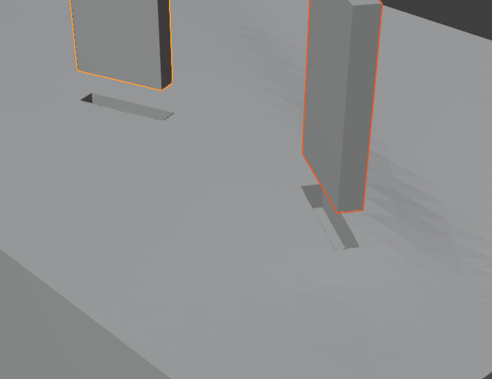
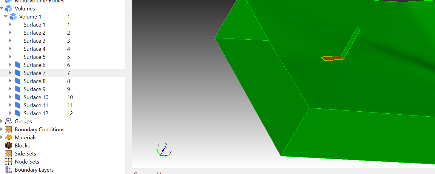
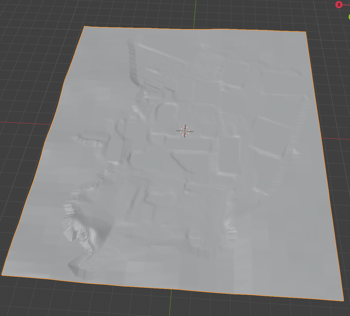
the two buildings and the ground layer are all in STL format.
- The bases of the buildings are flush with the ground surface.
https://transfer.coreform.com/qQeuXOc3eY/1.zip
#!cubit

reset

set developer commands on

import stl "stl_formatBox143Retopo_Slice.001.stl" merge

import stl "stl_formatBox143Box139.stl" merge

import stl "stl_formatBox143Box142.stl" merge

imprint vol all

merge tolerance 0.3

merge vol all

volume all size 3

volume all scheme sweep

mesh volume all

equivalence node all tolerance 0.15

draw hex all
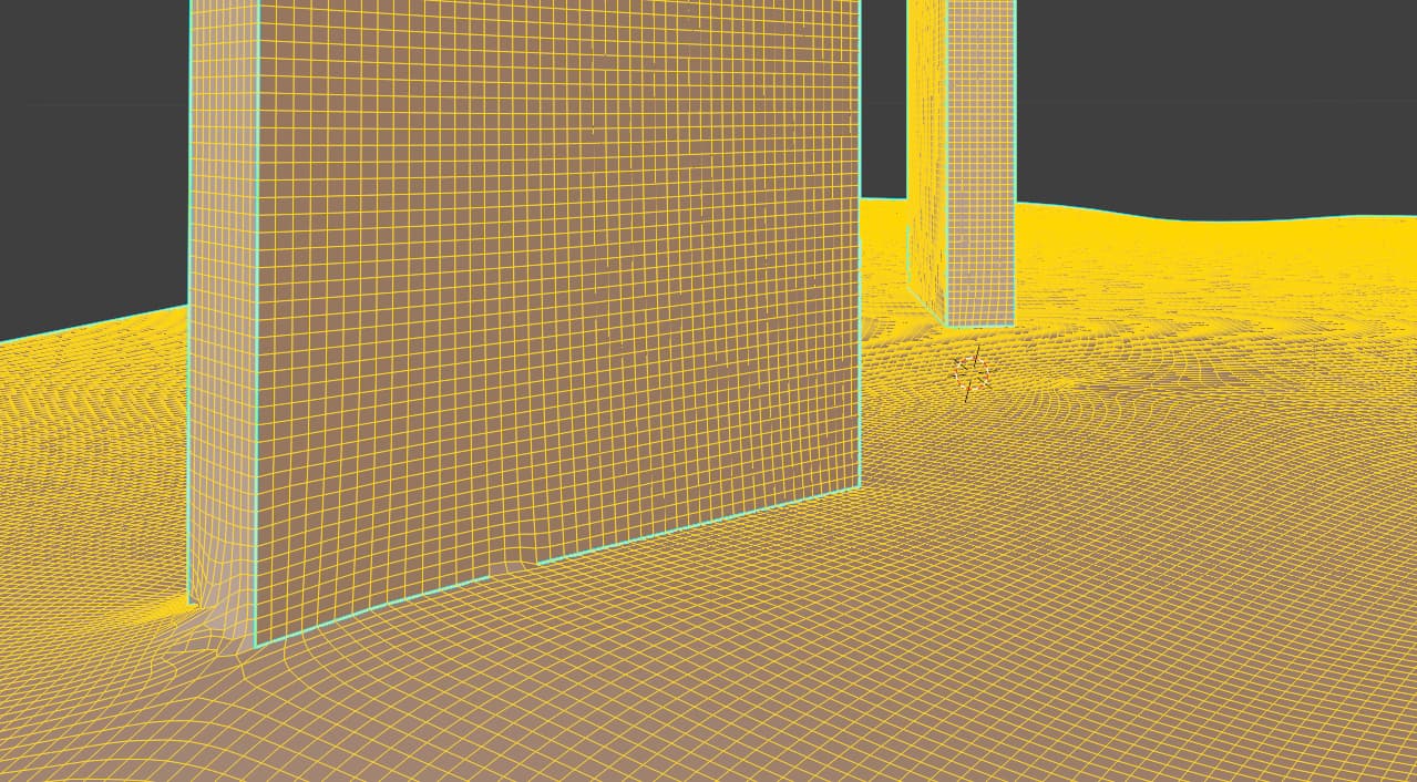
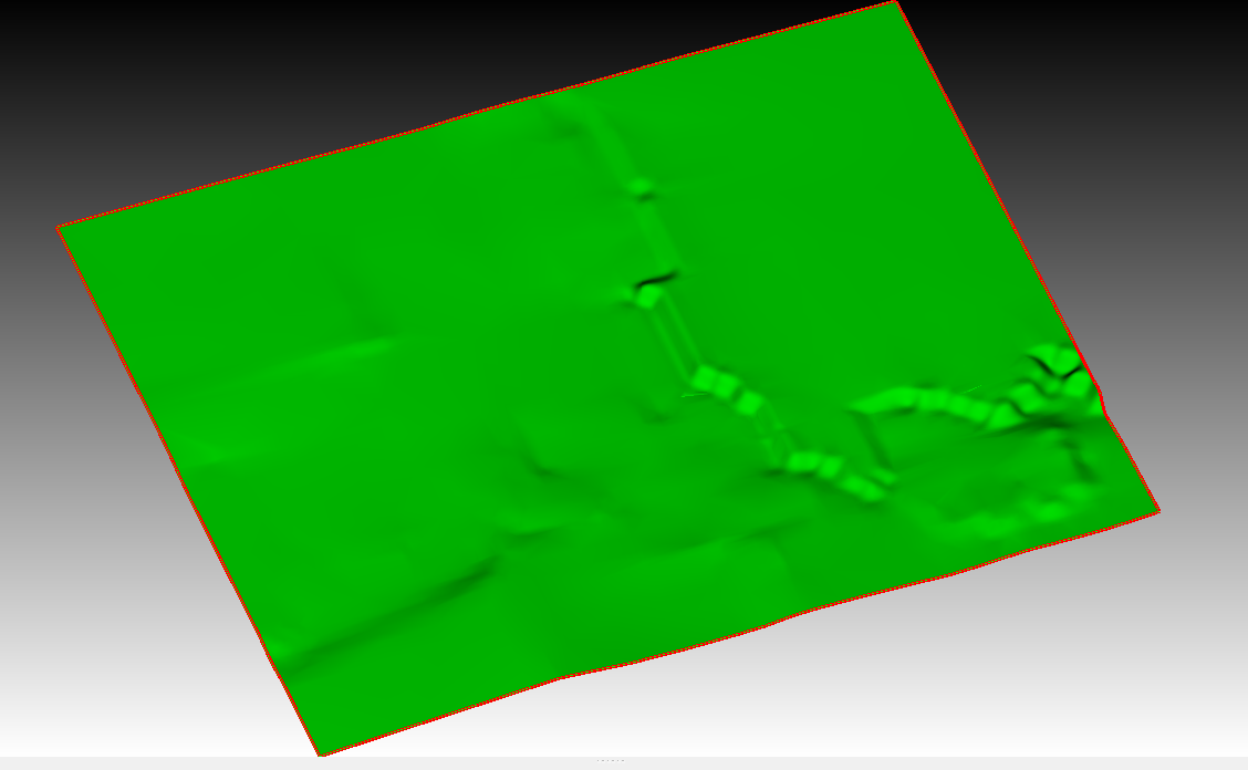
- The buildings are inserted into the ground layer.
https://transfer.coreform.com/wTYwHOgVmo/2.zip
#!cubit

reset

set developer commands on

import stl "stl_formatBox143Retopo_Slice.001.stl" merge

import stl "stl_formatBox143Box139.stl" merge

import stl "stl_formatBox143Box142.stl" merge

imprint vol all

merge vol all

volume all size 3

mesh volume all

draw hex all
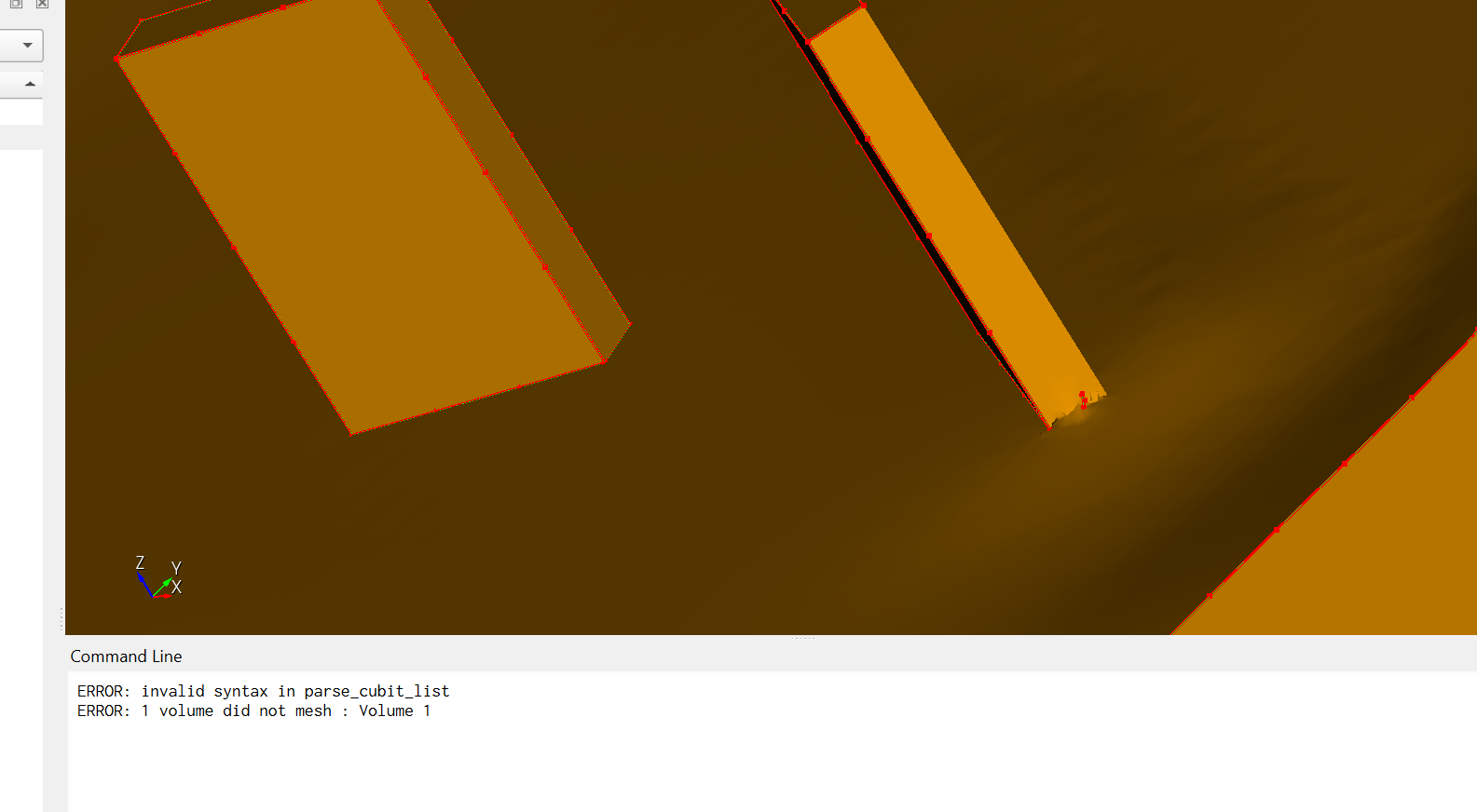
Cubit crashes when running the commands ‘imprint vol all’ and ‘merge vol all’.
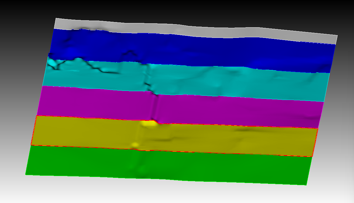
- Either ensure the buildings and the ground surface are coplanar, or remove the coplanarity.
https://transfer.coreform.com/12VdNQlNmD/3.zip
3.1 remove the coplanarity
3.2 with the coplanarity
I would like to obtain a continuous hex mesh for the buildings and the ground layer. Could everyone please help me?
I’m wondering: is it truly impossible to mesh STL files after importing them into Cubit? If that’s the case, I have a lot of white-model buildings and ground layers — how can I obtain a continuously coupled hex mesh for them?
Hello @aquanaut,
a lot of features are not available for faceted geometry but we can do at least basic boolean operations.
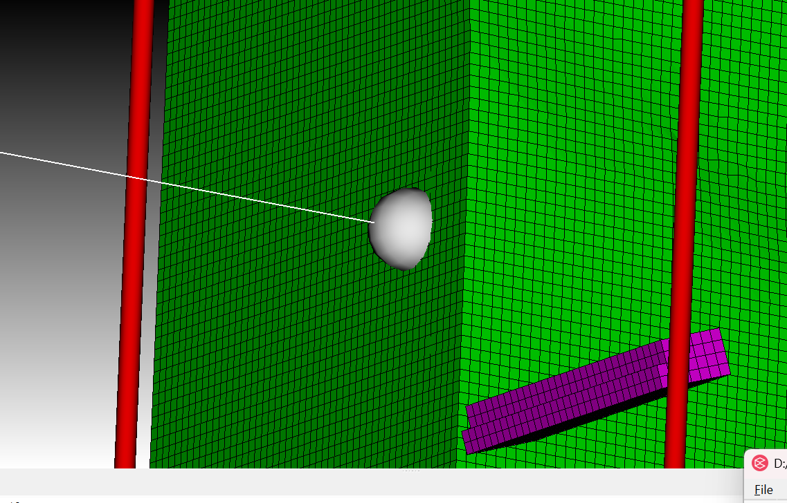
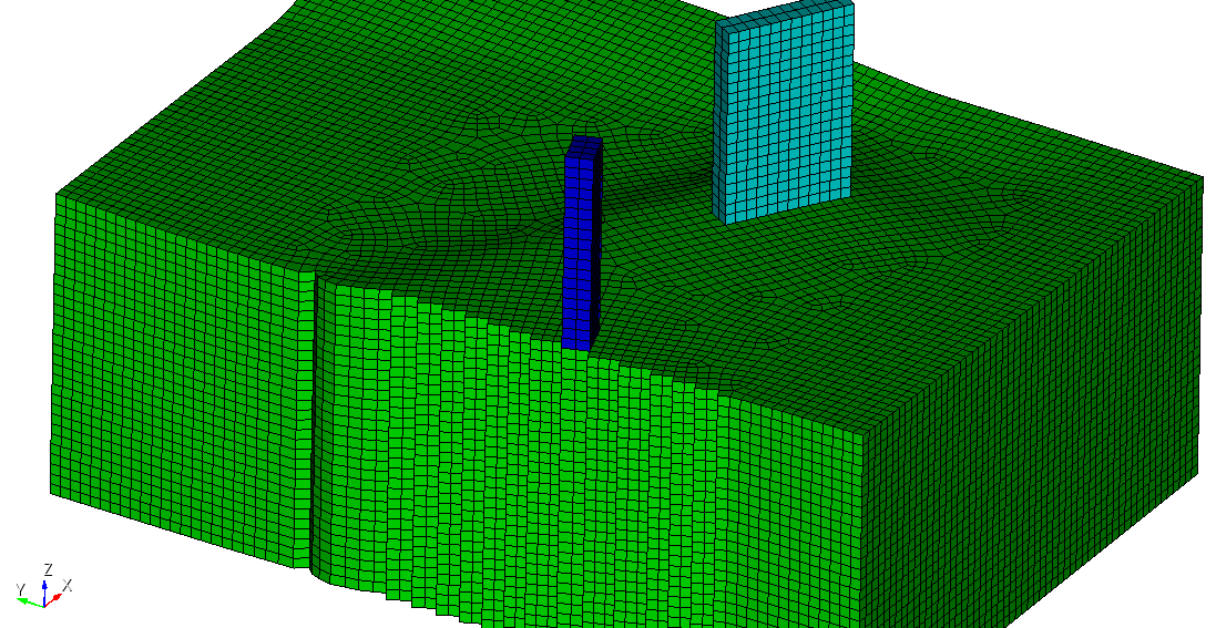
When i move the buildings into the ground surface and get rid of the intersecting volume, i can merge the volumes and mesh them.
#!cubit
reset
set developer commands on

import stl "stl_formatBox143Retopo_Slice.001.stl" merge
import stl "stl_formatBox143Box139.stl" merge
import stl "stl_formatBox143Box142.stl" merge

move Volume 2 z -2 include_merged
move Volume 3 z -1 include_merged
imprint vol all
subtract volume 1 from volume 2 3 keep
delete vol 2 3
merge vol all
volume all size 5
mesh volume all
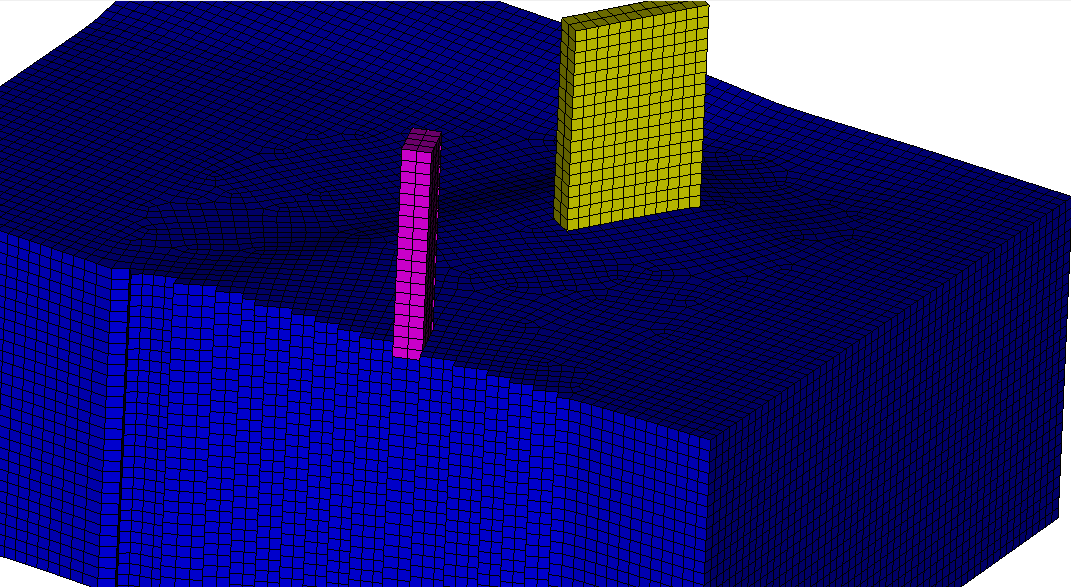
I can also insert the buildings into the ground surface this way.
#!cubit
reset
set developer commands on

import stl "stl_formatBox143Retopo_Slice.001.stl" merge
import stl "stl_formatBox143Box139.stl" merge
import stl "stl_formatBox143Box142.stl" merge

move Volume 2 z -5 include_merged
move Volume 3 z -5 include_merged
imprint vol all
subtract volume 2 3 from volume 1 keep
delete vol 4 1
merge vol all
volume all size 5
mesh volume all
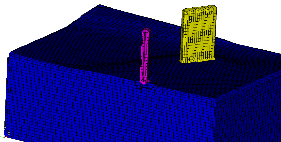
Using sculpt would also be an option to get a mesh.
#!cubit
reset
set developer commands on

import stl "stl_formatBox143Retopo_Slice.001.stl" merge
import stl "stl_formatBox143Box139.stl" merge
import stl "stl_formatBox143Box142.stl" merge

move Volume 2 z -5 include_merged
move Volume 3 z -5 include_merged
subtract volume 2 3 from volume 1 keep
delete vol 4 1

volume all size 5
sculpt volume all
draw block all
1 Like
Hi, Thank you very much  .
.
Since you said ‘a lot of features are not available for faceted geometry’, I exported the STL ground surface as a point cloud.
https://transfer.coreform.com/QWRrFVqiB3/cutter.stl
https://transfer.coreform.com/2SEcIiDUFH/cutter.csv
I took inspiration from the introduction in this link: Creating a surface from structured (x,y,z) topography data and meshing it - #3 by gvernon
https://transfer.coreform.com/20D2GIaJQy/skin_surface.py
I also tried generating a spline surface in the Y direction, but the accuracy is still quite different from that of the STL.
Using the stitch method:
https://transfer.coreform.com/UuamGglFJx/batch_skin.py
In order to obtain a ground surface with the same accuracy as the STL, I also tried the following:
https://transfer.coreform.com/QOSAOlmoCE/cutter_vertex.jou
https://transfer.coreform.com/DB842VXfdk/cutter_uv.jou
https://transfer.coreform.com/RnFI5neUFz/cutter_node.jou
https://transfer.coreform.com/wGrHiqSSQe/cutter_geom.jou
And also:
https://transfer.coreform.com/XaPf8XEMbd/cutter.inp
import abaqus mesh geometry "D:\SPECFEM\trial\5-2cutter\cutter.inp" no_geom
create mesh geometry surface all feature_angle 135
The S4 shell element has a front side and a back side, each generating a surface.
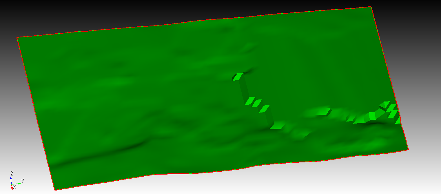
There are two issues here: perhaps the results I exported from the STL point cloud are inaccurate and not very consistent with the STL. Also, the ground surface is stitched together from different precisions and has a steep slope — I’m not sure if it can be flattened in Cubit.
For better testing, I am uploading a complete STL file.
https://transfer.coreform.com/0oW1M3BjAt/merged_aligned.fbx
If you need anything else, I’m always here.