Hi, I’ve been working on meshing a fairly complex geometry and noticed that covering the entire wall thickness with a boundary layer would simplify the process and provide better control over mesh quality. However, the boundary layer tool doesn’t seem well suited for meshing the full thickness of the geometrie. Even if I set the boundary layer depth to match the wall thickness, it doesn’t align perfectly. ( I’m selecting a suitable growth rate by solving an equation derived from the sum of geometric sequence.)
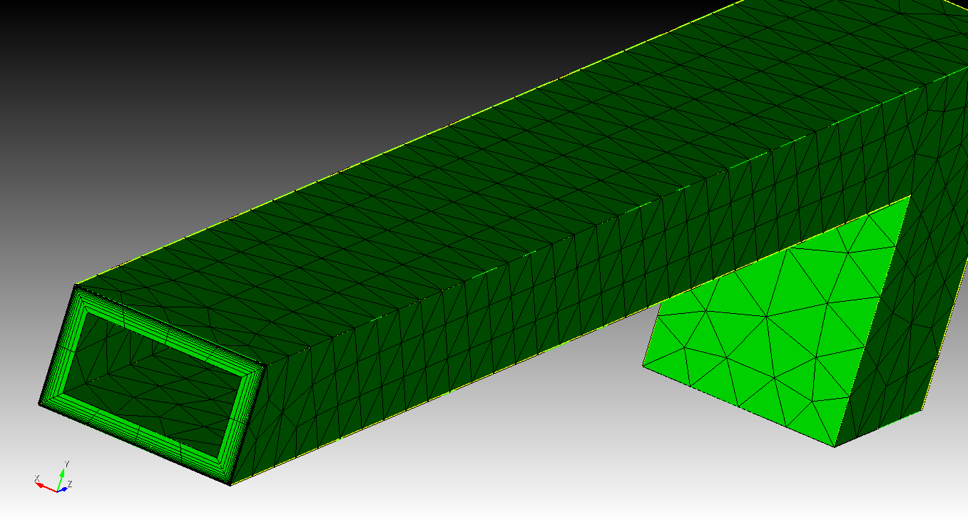
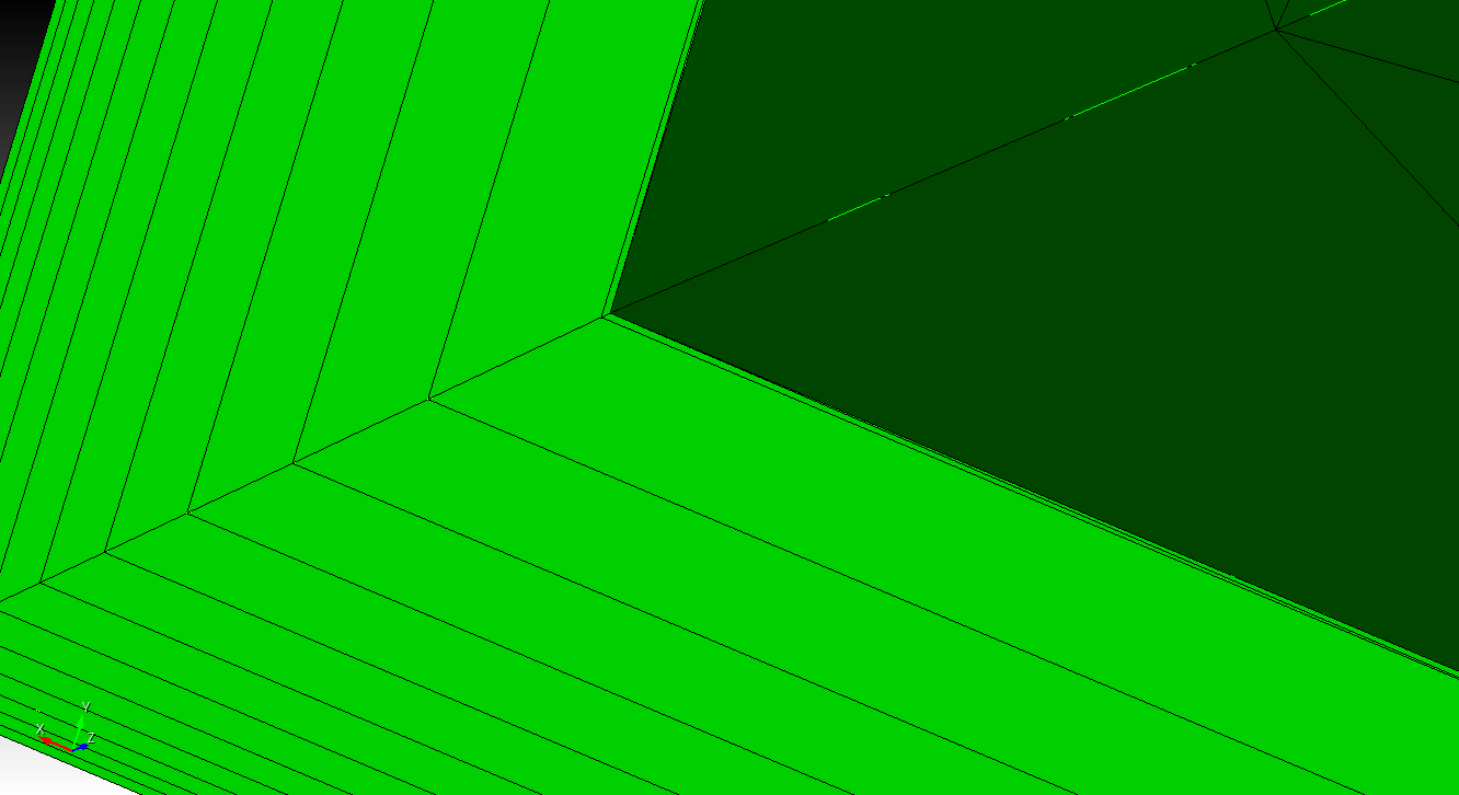
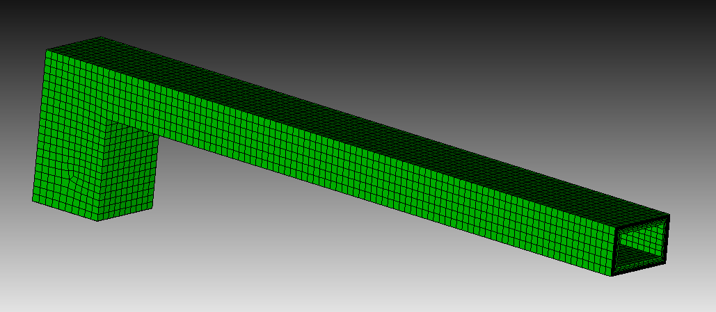
I attached a simplified version of my meshing script and a screenshot of the simplified geometry and mesh. I would appreciate any advice on how to approach this or how to make the boundary layer match the thickness reliably or a pointer to a tool better suited for my aplication (resolving skin effect). I also tried meshing the full geometry with a boundary layer, converting it into a mesh-based geometry, and removing the original solid, but this method often fails on the full geometry, even though a small error in dimentions would be acceptable for me.
Any guidance would be helpful.
journal file content:
reset
#geometry parameters
#{width = 0.02}
#{height = 0.012}
#{wall_thickness = 0.002}
#{length_p1 = 0.175}
#{length_p2 = 0.025}
#create the geometry
create surface rectangle width {width} height {height} zplane
create surface rectangle width {width-wall_thickness2} height {height-wall_thickness2} zplane
sweep surface 1 perpendicular distance {length_p1}
sweep surface 2 perpendicular distance {length_p1-wall_thickness}
create surface rectangle width {width} height {width} yplane
create surface rectangle width {width-wall_thickness2} height {width-wall_thickness2} yplane
move Surface 13 x 0 y {-height/2} z {length_p1-width/2}
move Surface 14 x 0 y {-height/2} z {length_p1-width/2}
sweep surface 13 direction 0 -1 0 distance {length_p2}
sweep surface 14 direction 0 -1 0 distance {length_p2} keep
sweep surface 14 direction 0 1 0 distance {height-wall_thickness}
unite volume 1 3
subtract volume 2 4 5 from volume 1
#mesh parameters
#{layers = 12}
#{first_row_height = 0.00003}
#{growth_rate = 1.2809061443676268}
#{mesh_size = 0.005}
create boundary_layer 1
modify boundary_layer 1 uniform height {first_row_height} growth {growth_rate} layers {layers}
modify boundary_layer 1 add surface 5 volume 1 surface 6 volume 1 surface 1 volume 1 surface 3 volume 1 surface 31 volume 1 surface 18 volume 1
modify boundary_layer 1 continuity on
volume 1 size {mesh_size}
volume 1 scheme tetmesh
mesh volume 1