Hi all,
First-time poster here, so if I’ve unknowingly broken any forum customs or etiquette, I offer a preemptive apology!
I’m using Coreform Cubit (2024.8) to draw a somewhat complex geometry and then generate a tet mesh with a boundary layer grown off of specific surfaces for a CFD simulation. Everything is going great regarding surface meshing, however, the volume mesh fails with an error that seems to have eluded both Google and the forums so far, at least from what I can find.
To troubleshoot, I’ve distilled the geometry down to a minimal viable version that still triggers the same issue. I’ve attached this script at the bottom of the post.
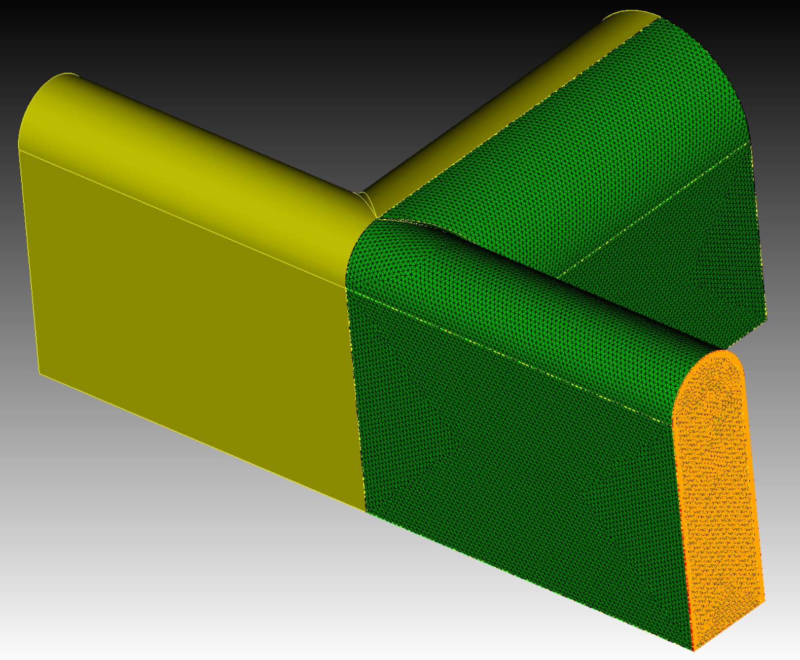
For reference, here is an image of the reduced geometry with the surface mesh shown - note that I am webcuting and reflecting half the volume here because one particular surface (highlighted in the attached image) needs to have an identical mesh to its mirrored counterpart. This is due to a periodic boundary condition requirement in the solver I’m using, which insists on a one-to-one mesh correspondence. It might be worth noting also that I am able to mesh the entire geometry when treating it as one monolithic volume - however this does not adhere to the surface constraint mentioned above.
The error that I am getting is this:
2 Reversal Nodes Found...
WARNING: Boundary layer on surface 15 is invalid.
ERROR: round_mesh_v5_2.jou, line 51. Volume 1 meshing unsuccessful using scheme: tetmesh
ERROR: round_mesh_v5_2.jou, line 51. 1 volume did not mesh : Volume 1
code here
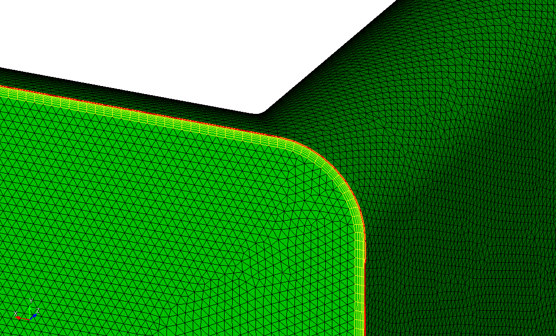
Here is a zoomed in image of what might be the problematic region (given that it is the most geometrically complicated part of the volume), with the offending surface 15 highlighted.
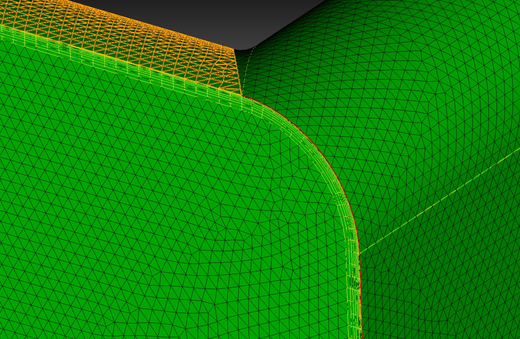
I have searched high and low for what a reversal node is in Coreform Cubit, but haven’t been able to identify what this actually is, and since I am not told what nodes are the offending nodes, I am at a loss as to how to try fix this issue.
At this point, I’m open to suggestions, tips, constructive critiques - or even commiseration. I’m still relatively new to Cubit this year, so it’s entirely possible this is a classic case of PEBKAC (Problem Exists Between Keyboard And Chair).
Thanks in advance for any help!
The example script:
# create geometry

brick x 20 y 10 z 10
create cylinder height 20 radius 5
rotate volume 2 angle 90 about y
move volume 2 y 5
unite volume 1 2
compress

brick x 5 y 12.5 z 40
move volume 2 y 1.25
create cylinder height 40 radius 2.5
move volume 3 y 7.5
unite volume 2 3
compress
move volume 2 x -10

unite volume 1 2
compress

# put a round on sharp edges

# {R=0.5}
tweak curve 19 fillet radius {R} {R}
tweak curve 20 fillet radius {R} {R}
tweak curve 22 fillet radius {R} {R}
tweak curve 24 fillet radius {R} {R}

# Webcut volume in half

webcut volume 1 with plane zplane
imprint volume all
merge volume all
compress

# define mesh size

surface all size 0.25
volume all size 1.0

# define boundary layer

create boundary_layer 1
modify boundary_layer 1 uniform height {1.5e-02} growth 1.25 layers 8
modify boundary_layer 1 add surface 4 5 10 11 12 15 16 17 volume 1
modify boundary_layer 1 continuity on

# generate mesh

volume 1 scheme tetmesh
mesh volume 1

save cub5 "checkpoint.cub5" overwrite journal

# copy mesh to the other half

volume 1 copy reflect z
volume 2 scheme copy source volume 3 nosmoothing
mesh volume 2
delete volume 3

# Set 2nd order elements

block 1 add volume 1 2
block 1 element type TETRA10
block 1 element type WEDGE15

# list model details

List Model

# export mesh

set exodus netcdf4 off
set large exodus file on
export mesh "mesh.exo" block 1 overwrite
save cub5 "mesh.cub5" overwrite journal