Hello Gili,
basically it sounds like all you need is already available.
If you have the ability to write out the displacements that you want, then i would suggest to just write them into a .csv and read them in a python script. You would just need to make a list/array in python that’s holding the node ids and its displacement data. You can then just make a loop and adjust the nodes.
in python it will probably look similar to this
# with node_disp holding the node ids and displacement data
# node_disp[0] node id
# node_disp[1] displacement in x
# node_disp[2] displacement in y
# node_disp[3] displacement in z

cubit.cmd("set developer on")
cubit.cmd("set node constraint off")
cubit.cmd("set graphics off")
for node in node_disp:
 cubit.cmd(f"node {node_disp[0]} move x {node_disp[1]} y {node_disp[2]} z {node_disp[3]}")

cubit.cmd("set graphics on")
Here is a code snippet in c++ how i do it in my calculix component.
  if (!ccx_iface->silent_cmd("set developer on")){return false;}
  if (!ccx_iface->silent_cmd("set node constraint off")){return false;}

  cmd = "graphics off";
  ccx_iface->silent_cmd(cmd.c_str());

  for (size_t i = 0; i < frd->result_block_node_data[data_id].size(); i++)
  {
    //node 1 move x 0.1 y 0.2 z 0.3
    cmd = "node " + std::to_string(frd->result_block_node_data[data_id][i][0])
    + " move"
    + " x " + ccx_iface->to_string_scientific(scale*frd->result_block_data[data_id][frd->result_block_node_data[data_id][i][1]][0])
    + " y " + ccx_iface->to_string_scientific(scale*frd->result_block_data[data_id][frd->result_block_node_data[data_id][i][1]][1])
    + " z " + ccx_iface->to_string_scientific(scale*frd->result_block_data[data_id][frd->result_block_node_data[data_id][i][1]][2])
    ;

    ccx_iface->silent_cmd(cmd.c_str());

    //update progress bar
    const auto t_end = std::chrono::high_resolution_clock::now();
    int duration = std::chrono::duration<double, std::milli>(t_end - t_start).count();
    if (duration > 500)
    {
      progressbar->percent(double(i)/double(frd->result_block_node_data[data_id].size()));
      progressbar->check_interrupt();
      t_start = std::chrono::high_resolution_clock::now();
    }
  }
  progressbar->end();
In your .vtu and .e that you send, i only see single tets that are not connected with each other.
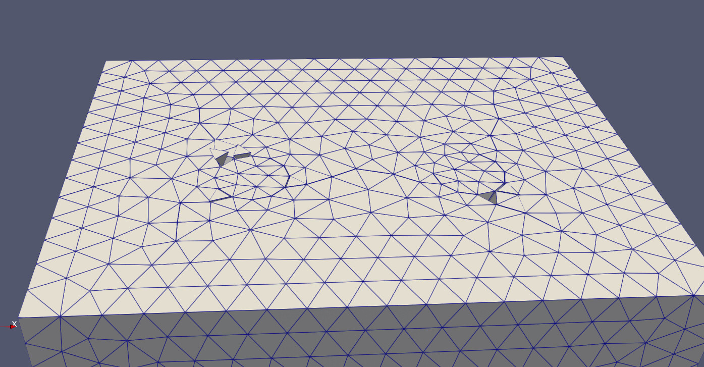
So my question here is, are you starting with a mesh that contains only unconnected elements?
Why are the elements not connected?
How does your starting geometry and mesh really look?
That’s the real issue here for me.
Normally i would create a classic unstructured mesh to work with. If your solver then outputs a mesh where all elements gets disconnected. It will get troublesome to map the node ids back onto the starting mesh. I don’t think that can be easily done. Some elements gets clearly disconnected, currently i can’t think of a good solution when there are some elements flying in space.
So i would rather remesh it like in this post.
When you import just the .e after the first run. Then we end up with mesh based geometry. Boolean operations on such geometry are still in development. So getting a united volume from all single tet volumes will most likely fail. We would need to think of other ways to unite the elements back before we could try to use sculpt.