Automating Complex Volume Subtraction with Problematic Geometry – Seeking Efficient Solutions

Hello,

I am working with Cubit and trying to automate a process involving volume subtraction, but I am encountering several issues related to problematic geometry. I would like assistance from an expert to understand how to resolve these issues efficiently, as doing it manually for each volume is not practical given the large number of volumes I am working with.

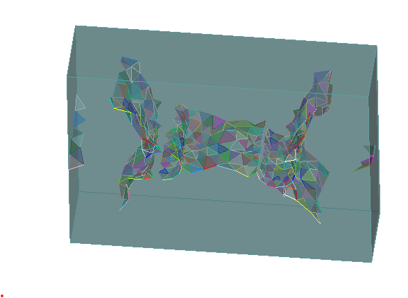
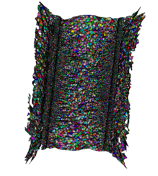
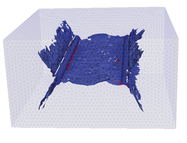
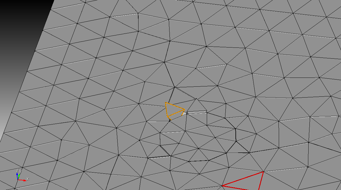
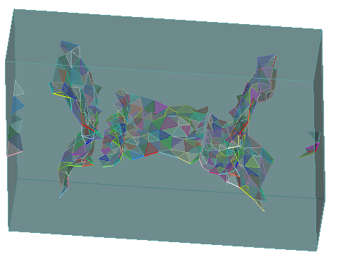
Objective: I have a set of solid volume elements representing a damaged state in my simulation. I created a new volume, and I want to subtract all the other existing volumes from this new volume. The outer shape of the subtracted volumes is essential as it represents a damage pattern crucial for my analysis. However, these volumes are problematic; they may:

  • Penetrate each other
  • Have small gaps between them
  • Be very thin or flat

While their geometry is imperfect, their overall arrangement is necessary to represent the damaged state accurately.

Steps I Followed:

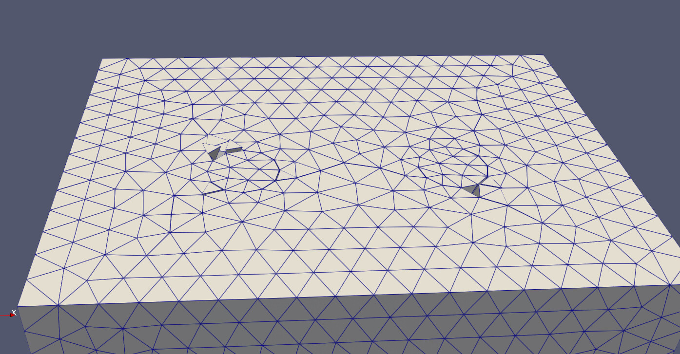
  1. Created a New Volume:
  • This is the volume from which I want to subtract all the other smaller volumes.

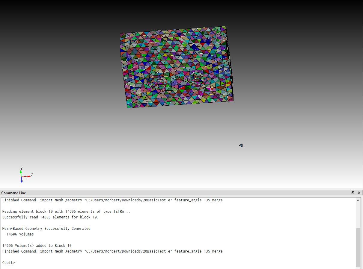
I’v attached the small example and the real volumes I need

  1. Subtraction Attempt:
  • Command: subtract volume [range of volumes] from volume [main volume]
  • This operation fails with several errors like:
    • Coincident face intersections
    • Non-manifold edges
    • Inconsistent face-body relationships
  1. Validation and Geometry Checks:
  • Validate volume all – Revealed multiple issues (zero volume, bad surfaces, duplicate vertices, bad edges, etc.)
  • Quality volume all – Highlighted thin regions and problematic areas.
  • Intersect volume all – Showed that some volumes intersect with each other.
  1. Manual Fixes:
  • Reversing surfaces for orientation issues.
  • Deleting and recreating volumes from surfaces.
  • Addressing individual volume issues (works but is not feasible due to the large number of volumes).
  1. Tolerance Adjustments:
  • Healer Default StitchMinTol 0.001
  • Healer Default StitchMaxTol 0.05
  • Healer Autoheal Volume all
  • tolerance boolean 0.001
  • This did not resolve the subtraction issues.
  1. Additional Checks and Attempts:
  • List edge all and list edge with problems.
  • Thicken sheet body all by 0.001 (did not work as they are solids)
  • Boolean unite volume all (failed with similar geometry issues)
  1. Partial Success:
  • When I manually fix specific problematic volumes and subtract them individually, it works.
  • When I attempt to subtract the entire range of volumes at once, I get error messages, but a new volume is still created. Was the subtraction fully successful?

Current Roadblock:

  • Manually fixing each volume is time-consuming and impractical for my large dataset.
  • Automated healing and tolerance adjustments did not solve the subtraction issues.
  • I need an efficient and automated workflow to handle these problematic volumes and perform the subtraction.

Request:

  • Are there any specific best practices or tools in Cubit to automatically resolve volume issues before Boolean operations?
  • Can the subtraction process be made more robust for imperfect geometries?
  • Is there a more efficient workflow to handle intersecting or nearly coincident volumes without manually fixing each one?
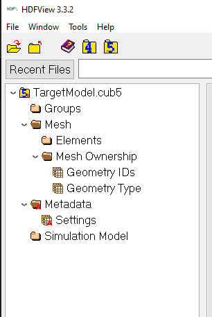
  • How can geometry be simplified? Is it possible to remesh a meshed volume? I converted the meshing to volumes because I didn’t find a way to remesh.

I would appreciate any advice or guidance on how to proceed. If needed, I am open to discussing this further in a Zoom meeting.

Thank you for your support!

Best,

Gili Lifshitz Sherzer
Small model just for quick testing

See attached to attempts to heal on a small sample, and the target model to repair and fix before subtracting, the best is to combine them into one volume before subtracting but this also didn’t work.
TargetModel.zip (257.1 KB)
AttemptsToHeal3NT.cub5 (4.9 MB)

Hello @sherzerg,
the target model seems to be empty. It doesn’t contain a geometry or mesh.
grafik

But i can open the second one. From what i see the geometry makes a lot of trouble and that most likely can’t even be fixed with manual work.

So the big question for me right now is, how are you creating or getting the volumes that you would like to substract.

For me it looks like you are running a simulation that got a tet mesh as input and you would need to erase specific elements (based on results) after each run. In this case it would be good to understand where your data comes from and how your final mesh should look. Could you give me a description of what you are trying to setup here.

Hi Norbert,

Thank you for your response and for looking into the models.

I am working on a project that involves post-analysis geometry reconstruction. The goal is to simulate a structure that has undergone damage, introduce rehabilitation elements into the damaged region, and then rerun the mechanical model on the updated structure to assess the effect of the repairs.

To give you a clear view of my workflow and the specific issue I’m facing, here are the steps I followed:

1. Initial Attempt:

After running the initial simulation, I tried to rerun the model with the deformed mesh as it is, but the solver flagged issues related to orphan elements, causing the run to fail.

image

2. Extracting the Damaged Geometry:

I imported only the damaged elements from the deformed mesh into Cubit and converted these elements into solid volumes to represent the cracked and failed regions.

3. Reconstructing the Surrounding Volume:

I then recreated the surrounding undamaged structure as a separate volume (representing the intact concrete) based on the original geometry but conforming to the damaged region.

4. Subtraction to Represent the Damage:

The next step is to subtract the damaged volumes from the reconstructed surrounding volume, leaving a void in place of the damaged geometry, or alternatively keep the damaged volumes integrated with the surrounding volume as distinct parts that will later be remeshed together, accurately representing the damage state

5. Final Meshing and Model Update:

After this subtraction, the plan is to remesh the resulting structure and introduce supporting/rehabilitation elements in the damaged zones before rerunning the mechanical analysis.

Key Issue:

The problem arises during the subtraction step. The deformed elements often lead to problematic geometries, such as:

· Penetrating/intersecting volumes

· Small gaps between volumes

· Extremely thin or flat features

These geometric issues frequently cause the Boolean subtraction operation to fail, even after multiple attempts with different approaches, including:

· Auto-healing and adjusting tolerances (Healer Default StitchMinTol / StitchMaxTol)

· Validating and analyzing volume quality

· Setting Boolean tolerances

· Manual surface reversal and volume recreation

· Working on individual volumes (which works but is not feasible due to the large number of volumes)

What I Need:

I’m seeking guidance on best practices or a recommended workflow in Cubit to handle post-simulation deformed geometries efficiently. I can also somehow recreate the geometry and remesh it.

If you have alternative approaches for transitioning from deformed mesh output to a clean, solid model suitable for further meshing and analysis, that would also be very helpful.

If you need to get rid of some elements, that’s also an option.

I have all the files from this process, so let me know if you need anything specific, such as the meshing file or solid elements of the surrounding undamaged structure.

I’m open to any suggestions you might have regarding the workflow or automated methods to handle the volume subtraction process in cases with complex or imperfect geometry.

The target model can be opened but its heavy file, I’m attaching its Step file that can be imported to Cubit.

[image]Target_Model001 (Solid).step

Target_Model001 (Solid)

Thanks so much for your help!

Best,

Gili

Hi @sherzerg,
i don’t have access to your share point. Could you please use https://transfer.coreform.com/ to share your file.

Could you also share the file that you are actually importing before creating the volumes? Also the mesh after your first run would be good.

I am currently not sure if your picture shows very malformed tets or if those are tris.

Hi Norbert,

Yes, you are correct, while working through the process, I identified an issue—when converting the extracted fracture geometry to the *e file, it seems to flatten the elements, which is a problem. I attached only the surrounding geometry in *e format (of a large cube jest to see if we have a solution), which can be imported into Cubit. (the file is attached to the email)

Since the fracture extraction process flattens the elements, I was wondering if there’s a way in Cubit to:

Convert the surrounding geometry into volumes, unite them, and remesh—so we obtain the post-fracture geometry while keeping its integrity.

Alternatively, peel the inner structure, keeping only the outer nodes, and remesh from them.

pre-processing the geometry may require Python within Cubit. Perhaps a loop over volumes could help extract the fracture surface.

I will appreciate any of your recommendations.

Thanks,

Gili

Hi Gili,
i opened the exodus file that you send via mail.

The tets aren’t sharing any nodes with their neighbours.

When i import the file and let the volumes create, i will get a volume for each tet because they are not connected.

I am really curious how your input mesh looks. Are you performing a simulation where the elements doesn’t share a node? Or is it because of the result output?
Or is you solver unmerging single elements when they are damaged enough?

We would either need a way to know the fractured elements and delete or deactivate them from the input mesh. Or the other option would be to somehow create a geometry that can be meshed. But think the a traditional tetmesh will probably not work here for remeshing. And i would either go for sculpt or something like in this post . Remeshing this way has the downside that the input volume size will not equal the output volume size. So we either win or lose tiny volume fractions.

If the deformations are stored in the Exodus file, you can use the Advanced Options on Exodus import and deform the geometry on import. From what Norbert mentions, you may also have to merge the nodes on import.

If the deformations are not stored in the Exodus file, you could use exodus.py to add them in.

Create this as mesh based geometry, delete the mesh and remesh the deformed volume with the tetmesher.

This is the general process. I haven’t looked at your specific problem.

Karl

Hi Karl,

Thank you for your suggestion regarding using Exodus import with deformation data. We have followed several steps to extract the deformed geometry from our simulation and integrate it into Cubit. However, we are encountering issues when trying to retrieve the displacement data from the Exodus file. Below, I will outline the steps we followed and the errors we encountered.

Steps We Followed:

  1. Exporting Deformed Geometry from ParaView (VTU Output)
  • Our simulation outputs the deformed geometry as a .vtu file in ParaView.

  • To extract the deformations, we applied the “Wrap by Vector” filter to reconstruct the deformed shape.

  • We then exported the modified dataset to an Exodus (.e) file via:

    • Save Data → Select Exodus Format

Ensured we included point data (nodal displacement).

  1. Importing the Exodus File into Cubit using the following commands :

  2. import mesh geometry “file path”

  3. set developer commands on

  4. list exodus variable

  5. The output we received:

  6. 0 global variables:

  7. 0 (heavy) Nodal Variables:

  8. 0 nodal variables for 1 mesh:

  9. 0 (heavy) Element Variables:

  10. 0 element variables for 1 block:

  11. 0 nodeset variables for 0 nodesets:

  12. 0 sideset variables for 0 sidesets:

  13. Checking Exodus File Contents in Python:

Findings: The file contains displacement-related variables (vals_nod_var1, vals_nod_var2, vals_nod_var3), but nodal deformation values are not recognized in Cubit.

  1. Attempting to Extract Displacement Data in Python

We attempted to extract vals_nod_var1, vals_nod_var2, vals_nod_var3 (assuming they correspond to X, Y, Z displacements).

Key Issues & Questions

  1. Exodus file does not seem to store deformation data correctly – how can we verify if the deformations are stored properly?

  2. Cubit does not recognize nodal variables on import – are there specific import settings we need to use?

  3. Python throws errors when extracting displacement data – is there an issue with how we are handling netCDF4 variables?

  4. Is there a way to manually add the deformed state into Exodus?

If the deformation data isn’t stored correctly, would exodus.py allow us to insert missing deformation values?

  1. We have an Excel file with node coordinates and deformations — could we use this to update the Exodus file and fix the missing data?

Next Steps

  • Do you have any recommended workflow adjustments for exporting VTU to Exodus while keeping deformation data?

  • Should we be handling displacement values differently in Python or Cubit?

Thanks for your time, and I appreciate any advice you can provide!

Best,
Gili

Hi Karl,
I hope you’re doing well.
I ran the Python code below to inspect the Exodus file, and it confirms that the deformation data is indeed included in the file. However, when I import the same Exodus file into Cubit, the deformation data does not appear to be recognized.
Python Code Used for Verification:
I used netCDF4 to inspect the Exodus file and check for nodal displacement variables. Here’s the script I ran:
python
from netCDF4 import Dataset
import numpy as np

Load the Exodus file

file_path = “E:/sherzerg/Chi/DCCiPost/DCInCWP_output/Run_2_2/wrapt vector deformed.e”
exodus_file = Dataset(file_path, mode=‘r’)

List all available variables in the Exodus file

print(“Variables in Exodus File:”, list(exodus_file.variables.keys()))

Check available nodal displacement variables

displacement_vars = [var for var in exodus_file.variables.keys() if “vals_nod_var” in var]
print(“Available Nodal Variables:”, displacement_vars)

Initialize displacement arrays

displacement_x, displacement_y, displacement_z = None, None, None

def extract_displacement(var_name):
“”" Extracts and ensures correct format for displacement data “”"
if var_name not in exodus_file.variables:
print(f"Warning: {var_name} not found in Exodus file.")
return None

data = exodus_file.variables[var_name][:]  # Load data 

# Check if it's a masked array and replace masked values with 0 
if isinstance(data, np.ma.MaskedArray): 
    data = np.ma.filled(data, 0) 

# If 2D (e.g., shape (1, N)), extract first time step 
if data.ndim == 2 and data.shape[0] == 1: 
    data = data[0, :] 

return data 

Extract and format X, Y, Z displacements

displacement_x = extract_displacement(‘vals_nod_var1’)
displacement_y = extract_displacement(‘vals_nod_var2’)
displacement_z = extract_displacement(‘vals_nod_var3’)

Print displacement shapes

if displacement_x is not None:
print(“Displacement X Data Shape:”, displacement_x.shape)
print(“Sample X Displacement:”, displacement_x[:5])

if displacement_y is not None:
print(“Displacement Y Data Shape:”, displacement_y.shape)
print(“Sample Y Displacement:”, displacement_y[:5])

if displacement_z is not None:
print(“Displacement Z Data Shape:”, displacement_z.shape)
print(“Sample Z Displacement:”, displacement_z[:5])

Close the Exodus file

exodus_file.close()
Python Output (Indicating Deformation Data is Present in Exodus):
When checking the nodal variables, I found:
exodus_file.variables[‘vals_nod_var1’][:]
Output:
masked_array(data=[[-1.12372438, -0.29971473, -0.55293966, …,
0.16673239, 0.02386141, 0.02470673]],
mask=False,
fill_value=1e+20)
This suggests that deformation values are correctly stored in the Exodus file.
Issue in Cubit: Deformation Variables Not Recognized
However, when I import the Exodus file into Cubit and run list exodus variable, the deformation data does not appear.
Cubit Output:
yaml
CopyEdit
IrazuCreator>list exodus variable

0 global variables:

0 (heavy) Nodal Variables:

0 nodal variables for 1 mesh:

0 (heavy) Element Variables:

0 element variables for 1 block:

0 nodeset variables for 0 nodesets:

0 sideset variables for 0 sidesets:

Finished Command: list exodus variable
This suggests that Cubit does not recognize the deformation data, even though it is clearly stored in the Exodus file.
Attached Files:
Exodus file (wrapt_vector_deformed.e)
Original VTU file (used for generating the Exodus file)
Key Questions:
Why is the deformation data present in the Exodus file but not recognized by Cubit?
Are there specific import settings required to load nodal variables in Cubit?
Would manually updating the Exodus file (e.g., injecting the deformations differently) help resolve this?
is there a way to confirm in Cubit whether nodal deformation data is being ignored or improperly mapped?
Next Steps:
Let me know if you have any insights on why this might be happening.
If you have any recommended steps to troubleshoot or manually adjust the Exodus file, I’d appreciate the guidance.
Would a Zoom call help to debug this together?
Thanks for your time!
Looking forward to your thoughts.
Best,
Gili

DCInCWP_Run_2_femdem.r3m_broken_joint_272160.vtu (428.0 KB)

Sorry this is the correct vtu file I sent in the emails, it is to large for this forom

Hello Gili,
basically it sounds like all you need is already available.

If you have the ability to write out the displacements that you want, then i would suggest to just write them into a .csv and read them in a python script. You would just need to make a list/array in python that’s holding the node ids and its displacement data. You can then just make a loop and adjust the nodes.

in python it will probably look similar to this

# with node_disp holding the node ids and displacement data
# node_disp[0] node id 
# node_disp[1] displacement in x
# node_disp[2] displacement in y
# node_disp[3] displacement in z

cubit.cmd("set developer on")
cubit.cmd("set node constraint off")
cubit.cmd("set graphics off")
for node in node_disp:
 cubit.cmd(f"node {node_disp[0]} move x {node_disp[1]} y {node_disp[2]} z {node_disp[3]}")

cubit.cmd("set graphics on")

Here is a code snippet in c++ how i do it in my calculix component.

  if (!ccx_iface->silent_cmd("set developer on")){return false;}
  if (!ccx_iface->silent_cmd("set node constraint off")){return false;}
  
  cmd = "graphics off";
  ccx_iface->silent_cmd(cmd.c_str());

  for (size_t i = 0; i < frd->result_block_node_data[data_id].size(); i++)
  {
    //node 1 move x 0.1 y 0.2 z 0.3
    cmd = "node " + std::to_string(frd->result_block_node_data[data_id][i][0])
    + " move"
    + " x " + ccx_iface->to_string_scientific(scale*frd->result_block_data[data_id][frd->result_block_node_data[data_id][i][1]][0])
    + " y " + ccx_iface->to_string_scientific(scale*frd->result_block_data[data_id][frd->result_block_node_data[data_id][i][1]][1])
    + " z " + ccx_iface->to_string_scientific(scale*frd->result_block_data[data_id][frd->result_block_node_data[data_id][i][1]][2])
    ;
    
    ccx_iface->silent_cmd(cmd.c_str());

    //update progress bar
    const auto t_end = std::chrono::high_resolution_clock::now();
    int duration = std::chrono::duration<double, std::milli>(t_end - t_start).count();
    if (duration > 500)
    {
      progressbar->percent(double(i)/double(frd->result_block_node_data[data_id].size()));
      progressbar->check_interrupt();
      t_start = std::chrono::high_resolution_clock::now();
    }
  }
  progressbar->end();

In your .vtu and .e that you send, i only see single tets that are not connected with each other.

So my question here is, are you starting with a mesh that contains only unconnected elements?
Why are the elements not connected?
How does your starting geometry and mesh really look?
That’s the real issue here for me.

Normally i would create a classic unstructured mesh to work with. If your solver then outputs a mesh where all elements gets disconnected. It will get troublesome to map the node ids back onto the starting mesh. I don’t think that can be easily done. Some elements gets clearly disconnected, currently i can’t think of a good solution when there are some elements flying in space.

So i would rather remesh it like in this post.

When you import just the .e after the first run. Then we end up with mesh based geometry. Boolean operations on such geometry are still in development. So getting a united volume from all single tet volumes will most likely fail. We would need to think of other ways to unite the elements back before we could try to use sculpt.

Hi Norbert,

Thank you so much for your response, the simulation starts were all elements are connected, they disconnect during simulation. When a crack opened then an interface wedge elements is add. But not all of them are supposed to be cracked and disconnected, it’s disconnect only the ones that I showed you in the beginning that I started with the broken elements in the middle. So my guess that all of them are disconnect because of the missing deformed shape. So I hope will found a solution to achieve based mesh delete it and Ramesh.
The elements that are have a large distance from the main ones can be just deleted

Thanks,

Gili

Hi Norbert,

Thank you so much for your response.

To clarify again, the pre-simulation model starts with all elements connected . During the simulation, elements disconnect only when a crack opens, and interface wedge elements are introduced at those locations. However, not all elements should be cracked and disconnected —only those that experienced failure. I showed you in the beginning that I started with the broken elements in the middle.
image

I assume that the missing, deformed shape in the process might cause all elements to be disconnected.

I will follow your suggestion and try adding the deformations to the mesh as you described, using Python to update the node displacements. However, I want to clarify:

  • If the volumes remain as single, unconnected tet elements after adding the deformation data, is there a way to reunite them?

  • Can healing and uniting nearby vertices help resolve this issue?

  • Would re-meshing work if the vertices are merged properly?

  • If not, does that mean there is no way to unite the volume into a continuous volume for further processing?

Regarding disconnected elements in space

  • I agree that elements with a large distance from the main structure can be deleted without an issue.
  • However, do you have any recommendations for reconstructing a valid mesh from the elements that should remain part of the model?

My concern is whether there is any possible solution to unite these elements after deformation or if adding the deformations will still result in an unusable set of separate tetrahedral volumes.

I am looking forward to your insights on this!

Best,

Gili

Hi Gili,

For the disconnected element issue. You could try importing the mesh just as free mesh, do not create any geometry. Then equivalence the free mesh at an appropriate tolerance for your model. You should be able to assume that nodes that should stay connected deform equally.

Here is a small script that reads an Exodus II file that has deformed geometry using the exodus python interface. You can run this from inside Coreform Cubit or from the journal editor.

#!python
import exodus
exo = exodus.exodus('C:/Users/kgmer/cubit/cubit_test/deformed_geom/out5.bin.exoII', mode='r')
nodal_variables = exo.get_variable_names('EX_NODAL')
time_vals = exo.get_times()
last_step = len(time_vals)
print(f'Last Time Step: {last_step} at {time_vals[last_step -1]}') # zero based array
print(f'Nodal variables: {nodal_variables}')
exo.close()

There are 30 time steps in this simulation. The last step is ~.3e-6 seconds. The nodal variables are named

'DMX', 'DMY', 'VX', 'VY', 'PRESSURE'

Looking at the import exodus code, the displacement variables must start with a D and end with X, Y, or Z. You can also use the exodus.py methods to write to the file. See exodus module — SEACAS 2024/08/17 documentation for the exodus.py methods. You would want to use the put methods to add to an existing file. You might also be able to rename the variable names in Paraview.

If you can make sure your nodal variables are named correctly you can use the Cubit methods to import the mesh.

The import steps would be something like:

import mesh 'file.exo' no_geom deformed step last
equivalence node all tolerance 1e-6
create mesh geom hex all wedge all
delete mesh
volume all scheme tetmesh
mesh volume all

Karl

Hi Karl,

Thank you for your detailed response and the provided script.

Here are the steps I took and the issues encountered:

  1. The commands seemed to create a volume from the outside geometry contour, resulting in other unsatisfactory mergings.
  2. i Used TET instead of HEX in the command ‘create mesh geom hex all wedge all’. (The file I tried with the commands you provided is attached so you can review it.
    remesh.cub5 (1.4 MB)
    )
  3. Tried using HEX but encountered an error: ‘ERROR: mesh creation failed’.
  4. I’m struggling with downloading exodus.py. I have tried downloading it manually, but it didn’t work.
    Could you please advise on what steps I should take next to resolve this?

I appreciate your insights and look forward to your guidance on this matter.

Best,

Gili

Hello Gili,
i also tried to remesh it but also failed. The mesher complains about overlaps and i don’t have a solution how to handle them.
I think the modification of the mesh in the solver probably needs to be adjusted. Or at least it must be trackable what actually gets modified to be able to redo the mesh modifications in cubit.

Does your solver also handle hexes?

About the exodus.py, i believe it is packed in the delivered python.
In cubit try

#!python
from exodus import exodus as exo
dir (exo)

to import the module.