My name is Ben Taylor, and I am currently a student at BYU studying Mechanical Engineering. I was taking ME EN 203, Mechanics of Materials, with Michael Scott when I was first introduced to Coreform Cubit. I ended up doing a little research on the Coreform.com website and downloaded the Free Coreform Cubit Learn. From their, I applied for a job with Coreform and began onboarding recently. Since I have a history in Solidworks, I was interested in this software and figured it would be similar, if not easier to learn. I have decided to post about my experience trying to learn Coreform Cubit and will try to share my confusions, encountered problems, and misconceptions.
After installing the software, I opened it up and played around with it a little bit. A few co-workers told me Coreform had created tutorials to help with learning Coreform Cubit, which I found very useful in starting (I also became the person in charge of updating them coincidentally). You can access these tutorials by going to Coreform.com. From there go to the “support” tab in the top right corner. You will then want to click on “Cubit tutorials”. This should take you to a page with a bunch of videos, pdf files, and downloadable files. I scrolled down to the “Step-by-step tutorials” and started with the first PDF file called, “Getting Started Tutorial”. Going through these tutorials will help you understand what is going on and why different steps need to be taken in order to get a quality mesh.
I started with the Cubit 100 tutorials and went through the first ones quickly. The first few are basically just showing you the controls and the location of everything. You eventually get to meshing parts and this is what I started to find the most useful but also the hardest to wrap my head around. I think the ‘knuckle.sat’ was a good example of where I need to webcut and what kind of features I need to think about removing. It is clear from doing this that small fillets and details don’t mesh well so they can just be removed for the purpose of meshing. I also learned where a webcut needs to happen. Slide 7 of the lecture 6 powerpoint was extremely useful in explaining the types of webcuts
. The idea of webcutting is new to me and the type of webcuts are also completely foreign (I’ve never seen this in any CAAD program). There are so many options and matching a picture to the type of webcut makes a big difference.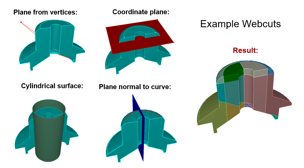
Once getting this far, I went back to Solidworks and created very simple parts. For example, I made 2 cylinders that connected, a rectangular hollowed out block, etc. (I am aware you can also make objects within Cubit itself but I personally can design things very quickly on Solidworks). After importing these parts, I would figure out how and where to webcut to eventually get a good mesh. Once I felt comfortable with these simple parts, I kept moving forward with the powerpoints.
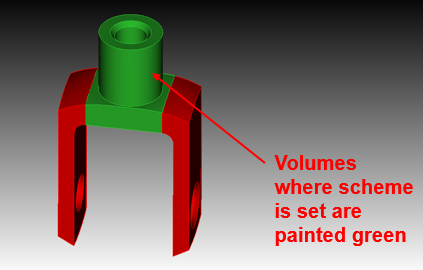
Within Cubit 100 there are 2 PowerPoints in specific that I think might be the most valuable, especially to any new users. These PowerPoints are lectures 7, ‘Power tools’, and 8, ‘ITEMS’. Power tools basically just helps find features that are not good for meshing. In the example it has you import and mesh, you will find that some of the small curves and fillets on the part need to be removed. The next step is web cutting the volume to get a good mesh. There is a scheme analyzer that turns all volumes, without a scheme set, red. When the scheme is set, the correlating volume will turn green. When all the volumes turn green, the part is good to go. I highly recommend spending extra time on this power point to really grasp these tools.
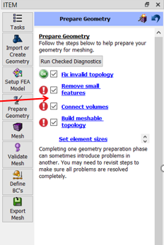
The ITEMS power point is also extremely useful. If you have no previous experience with cubit, I think this is the best thing to figure out first. It guides you through all the steps to get a good mesh. It seems to automate as much of the process as possible. There is a ‘Prepare Geometry’ tab and it evaluates the part and gives you a red exclamation point or green checkmark in 4 sections signifying whether it is finished or not. Once you go through all 4 sections and get 4 green checks, you can mesh the part. This process is very simple and user friendly.