It is often the case that a user wishes to query specific values, throughout a simulation. It is clear how one would query solution values (e.g. displacement, temperature): place a node at the point of interest and track the dof(s) for that node. It is less clear how to track derived values, which are often associated with quadrature points. The methods I see most often are:
- Grab the value associated with the element (valid when using 1 QP per element)
- Grab the value associated with the QP (for >1 QP per element) closest to the point of interest (requires knowledge about QP location in reference or current configuration.
- Extrapolate / project values from QPs to point of interest
Here’s what I think would be really useful: Highly-accurate, mathematically rigorous means of capturing values at arbitrary locations - independent of the mesh. I think there should be two flavors that make themselves conducive to verification and validation purposes – both of which are useful for analysts.
Verification: I have a mathematical model, verify my numerical method agrees with closed-form solution.
- Specify a position in the reference configuration and select desired values (solution or derived values)
- Track the values associated with this position by mapping the geometric location from the reference to the current configuration.
Validation: I have real world experimental data, usually gathered from the final deformed geometry and I want to compare simulation values at this location in the desired current-configuration – I don’t know what point in the reference configuration will eventually map to this location. Note that the desired current-configuration could be the final timestep, or could be an intermediate timestep. FWIW, in-situ measurements are generally more-rare, more-expensive, and lower-accuracy than post-experiment measurements.
- Specify a position in the current configuration (this location might vary vs time) and select desired values (solution or derived values)
- Track the values associated with this position by evaluating the desired current configuration.
As an example of the verification problem, consider the following example from Roark’s Formulas for Stress and Strain:
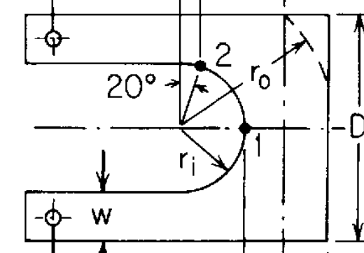
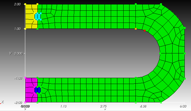
The goal is to compare the ratio of stresses between points 1 & 2 in that diagram. Note that point 2 is offset from tangency of the semi-circle and line by 20o. Note also that both points lie on the boundary. It would be nice to not have to have a mesh that places mesh nodes at both the point of tangency and at point 2. Instead it would be nice to place a point in the reference configuration (i.e. the red dot):
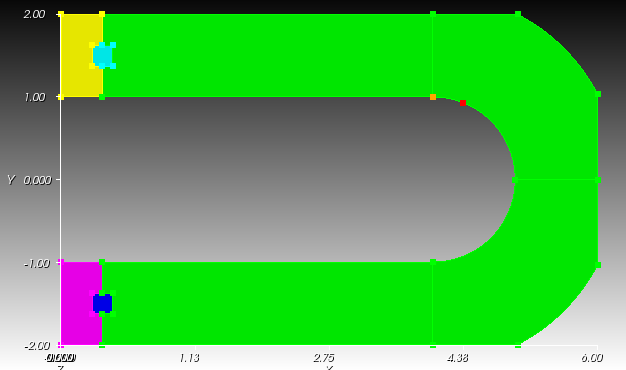
That is independent of the mesh: