
Thank you for your help, that worked. I still need to improve the geometry of the mesh for the model. Do you have suggestions of what additional things to do? Journal and quality files both attached.
geometry_only copy.txt (155.4 KB)
quality.txt (1.5 KB)
I have tried different tetrahedra sizes on the surfaces in the mesh (for the two groups I am meshing with different sizes) without significant differences in quality.
Have you noticed that after
the volumes are already hex meshable?
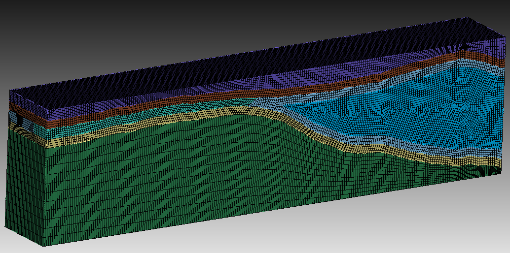
a few sizing functions before meshing should greatly help you get the mesh in your desired quality.
I am using tetrahedra but I assume your point still stands?
if a hex mesh is not an option. We can go on with getting a better quality for the tet mesh if thats okay for you.
do you have specific size and quality requirements that you need to achieve?
A hex mesh is not an option. I need a size of around 100 on surfaces 90 105 123 124 and then it can decrease monotonically away from those. Thank you for your help
the surface numbers are not valid anymore after the rebuild.
are you needing the merged surfaces? would be surface 83 117 121 116 111 118 95 126 101
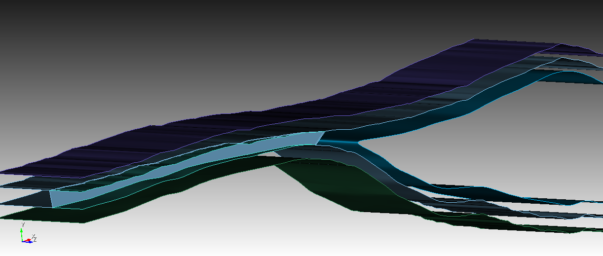
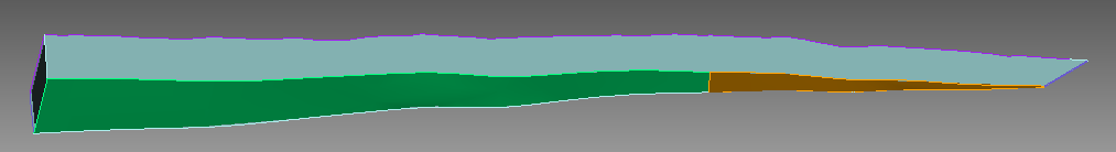
That’s strange, I had gotten the numbers after the rebuild. It is the dipping surface in the middle and the two vertical surfaces in contact with it. I have highlighted the curves associated with the surfaces of interest in the attached screenshot. Thanks!

i have now meshed it with size 100 for these surfaces. you could easily change the size for the surfaces in the journal file if those are not the correct surfaces. i hope this runs at your site, i’ve run it a few times now without an error.
forum.jou (155.5 KB)

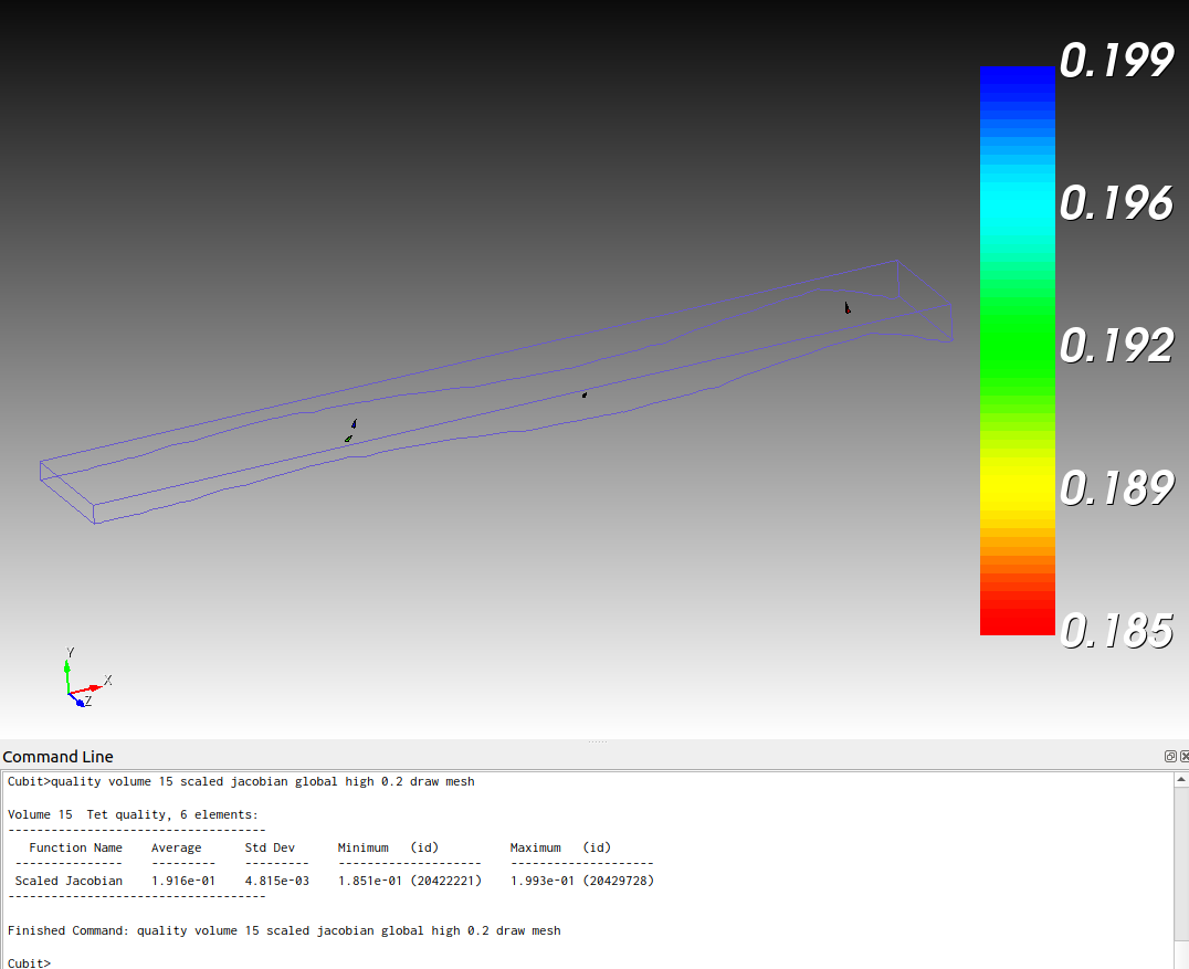
if some volumes have a too bad quality for your purpose than you will have to set a smaller mesh size for them. that’s why volume 15 has a smaller mesh size.
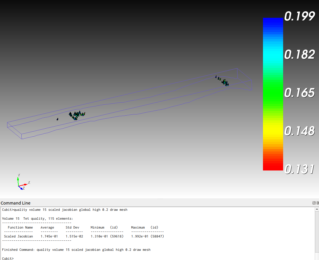
if that’s still too bad you can remesh it.
delete mesh vol 15
volume 15 size 500
mesh vol 15
quality volume 15 scaled jacobian global high 0.2 draw mesh
I have decided to remove two of the volumes to simplify the mesh but I am still getting some tetrahedra with poor quality shapes on volume 13. Do you have advice on further improving the mesh for that volume? I also would like the mesh to decrease in element size at a slower rate, so that the element size near the edges is smaller than it currently is.
geometry_only copy.txt (156.3 KB)
The journal file is attached.
WARNING: >>>>Poor Quality Shape Tet Generated!<<<< on Volume 13
(For example, the Shape metric for Tet 498575 is 0.0870208 .)
The threshold for a Tet is 0.2
Thank you for your help
Hi @p89on,
you will have to set the pave scheme for the top and bottom surface from volume 13.
Otherwise the quad mesh has already a terrible quality.
The other thing is, you have again the sharp tangency on volume 13.
I will cut off the tip right before the imprint and merge. You can either mesh the volume from the tip or make a bool operation with volume 15 like before. I would rather do the second as i expect a better mesh quality from that.
...
healer autoheal volume all rebuild

split curve 133  distance 200 from vertex 2914
split curve 137  distance 200 from vertex 2914
split curve 125  distance 200 from vertex 2908
webcut volume 13  with plane vertex 2935  vertex 2936  vertex 2937
unite volume 15 16

Imprint all
merge all
...
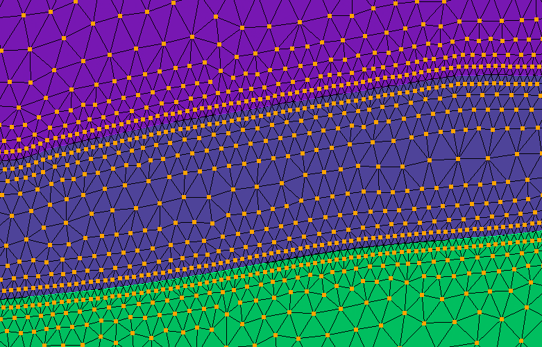
To control the element size you could for example mesh everything with a coarser mesh. And refine afterwards to your desired size.
forum_1.jou (157.4 KB)
Or you could also set a different mesh size for the surfaces and volumes and control the tet growth to manage the transition from big to small element sizes. Which i would expect to produce a better element quality.
forum_2.jou (157.5 KB)
Thanks for the recommendations, controlling the tet growth with the different sizes for surfaces and volumes yielded better element quality as you suggested. I will play around with different size options to see what does best for my problem.
I am currently interested in removing the nodes of the curves that cut all orthogonal surfaces in the bottom part of the mesh (z negative) from the nodeset that contains all the orthogonal surfaces. Even though the following code runs, the nodes still appear to be part of the nodeset. I attach the journal file and here’s the code snippet:
nodeset 2 remove node in curve 114 in surface 56
nodeset 2 remove node in curve 141 in surface 65
geometry_only copy.txt (155.6 KB)
You can only remove entities from a set if you first added them.
So if you add surfaces you can only remove those surfaces from the set but not specific nodes that are connected with the surface.
To do that you have to assign the nodes in an entity. Then you can specifically remove them.
In your case this should do it.
nodeset 2 add node all in surface 56 65 75
nodeset 2 remove node all in curve 114 141
Hi Norbert,
Thanks for your continued help! I removed the nodes as you suggested.
Despite the improvements the mesh’s topology is still not good enough for my finite element model. Do you have recommendations to further improve it? Journal file attached.
Thank you
geometry_only copy.txt (155.6 KB)
Could you please first point out the mesh requirements you need to fulfill for your model. It’s hard too improve something when i don’t know what requirements you must reach.
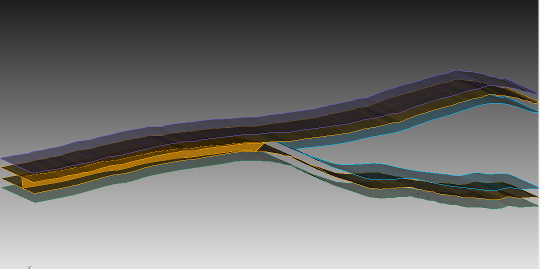
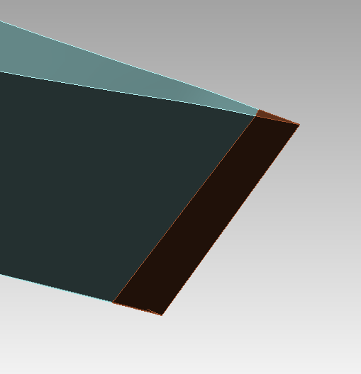
One improvement I think would be to add an additional surface as shown in the screenshot, since I only want to use a subset of the bottom surface of volume 13 in the model (as illustrated in the screenshot), so that I can treat it separately from the entire bottom surface.
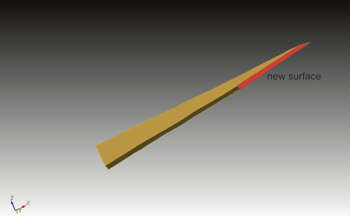
Similar to the cut at the tip, you could split the surface. Don’t forget to assign the pave scheme after the imprint and merge.
...
split curve 126  distance 15000 from end
split curve 128  distance 15000 from end
split surface 80  through vertex 2945 2946

Imprint all
merge all
Surface 78 88 89 scheme pave
...
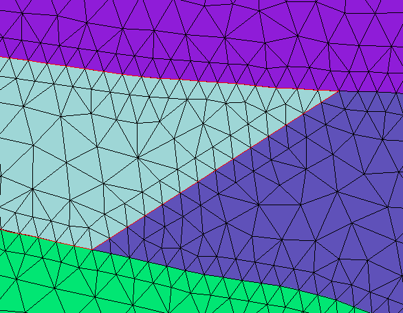
I am struggling to understand which of the surfaces should be paved (example of one of them where the paving makes funky patterns, where I’d like the cell sizes to be constant except for where they approach surface 53, already meshed finer). If paving generally makes better geometries for non-planar surfaces, is there a reason to ever not use the pave scheme?
Thanks for your help. My journal file is attached.
works_paved.txt (155.7 KB)

The reason why i used the pave scheme was to get more control of the mesh size and quality. After the cut i made at the sharp edge, there were only surfaces with 4 corners, so they could ideally be mapped as they were just skewed rectangles. But the mapped scheme would have resulted in an initially bad element size and shape distribution.
Consider this short example.
reset
create vertex x 0 y 0 z 0
create vertex x 10 y 0 z 0
create vertex x 10 y 0.1 z 0
create vertex x 0 y 4 z 0

create curve vertex 1 2
create curve vertex 2 3
create curve vertex 3 4
create curve vertex 4 1

create surface curve all with is_free

sweep surface 1  vector 0 0 1  distance 2
webcut volume 1 with plane xplane offset 8

imprint vol all
merge vol all

vol all size 0.2
#surface 9 scheme pave

mesh vol all
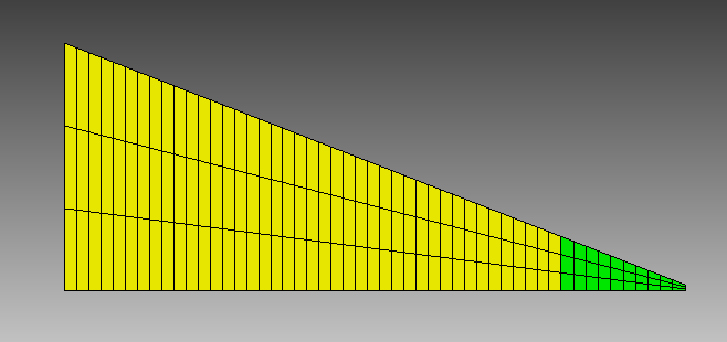
and with the pave scheme for surface 9
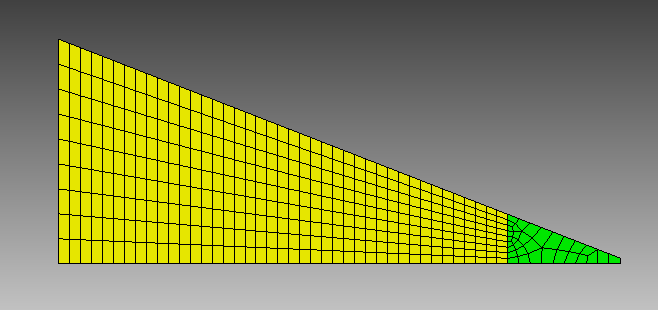
without the pave scheme the controlling of the mesh size from the adjacent surfaces would be more troublesome.
I personally use the pave scheme rather for mesh size transitions and for non trivial surfaces that i don’t want to decompose further. If you have surfaces like some skewed rectangles or triangles than i would not really use the pave scheme unless the mapped and triprim scheme will result in a bad quality or undesired shapes and sizes.
The schemes work perfectly too on spline surfaces like here the mapped scheme.

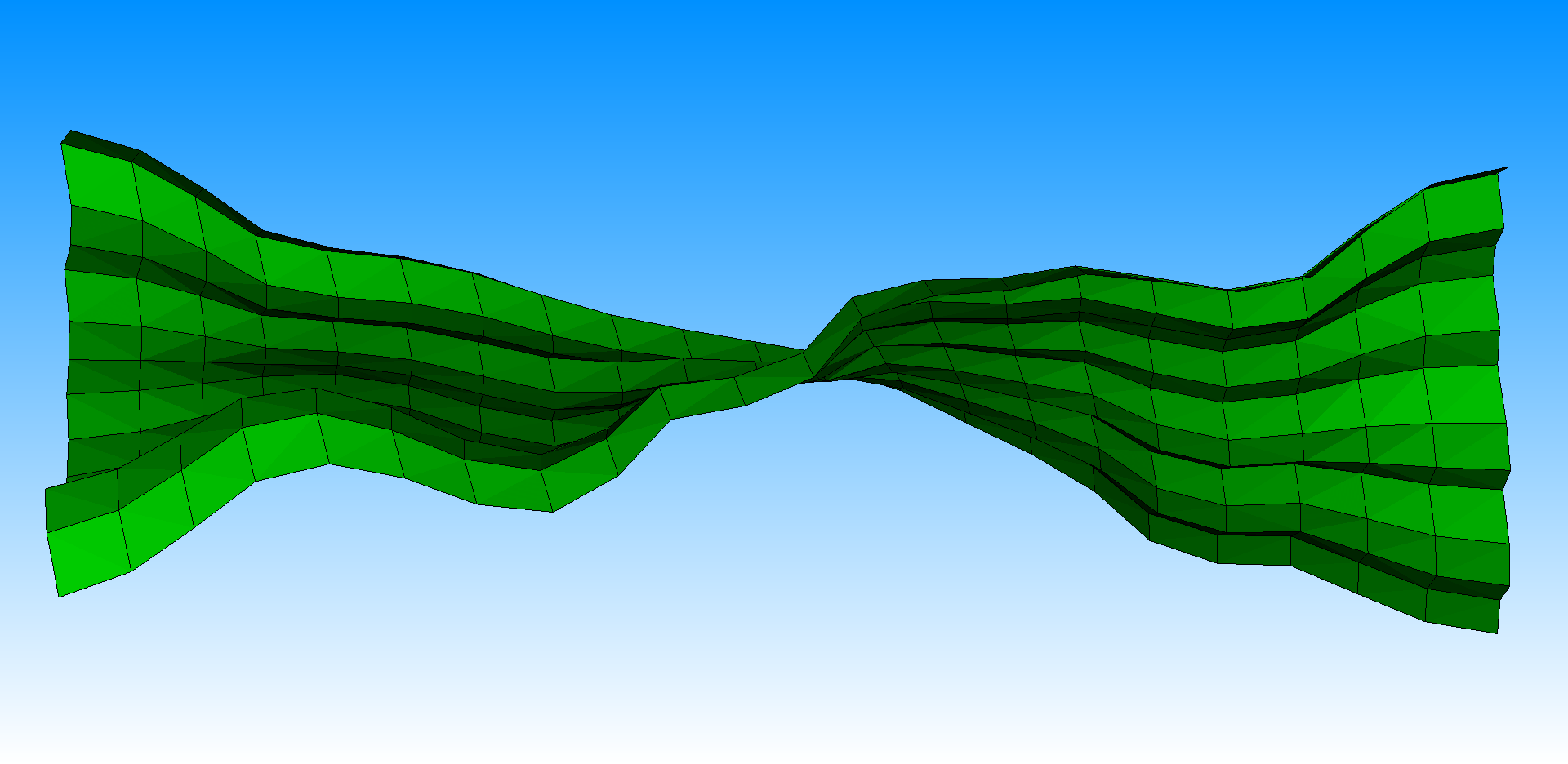
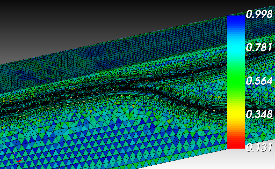
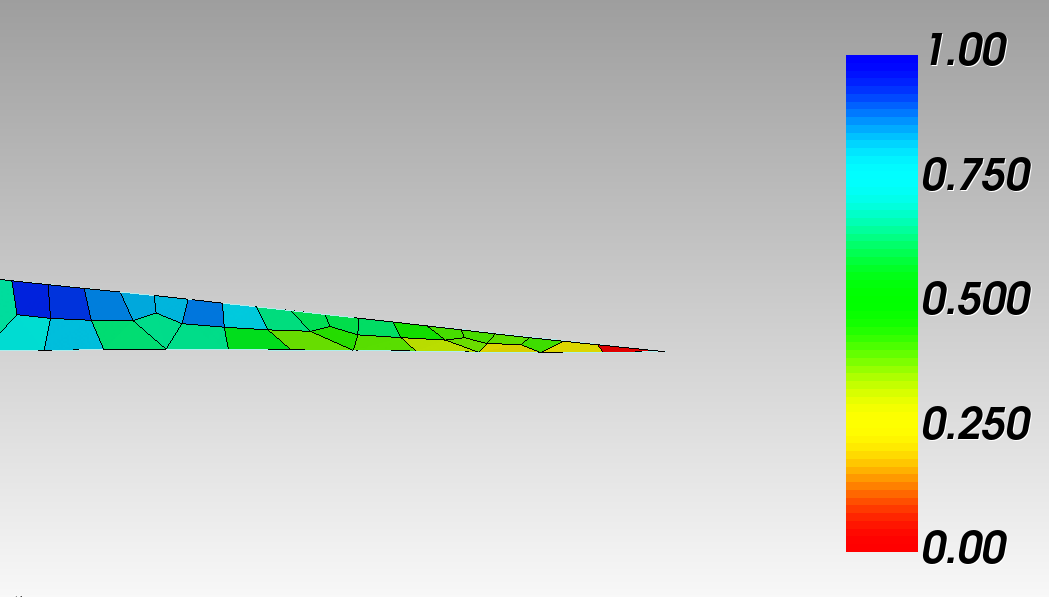
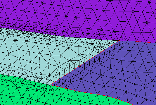
thanks for the thorough explanation, it is helpful. When I remove the paving scheme from surfaces 53 and 65, I end up with a series of very distorted cells (See screenshot), do you have advice for mitigating this?
thank you
works_paved.txt (155.7 KB)
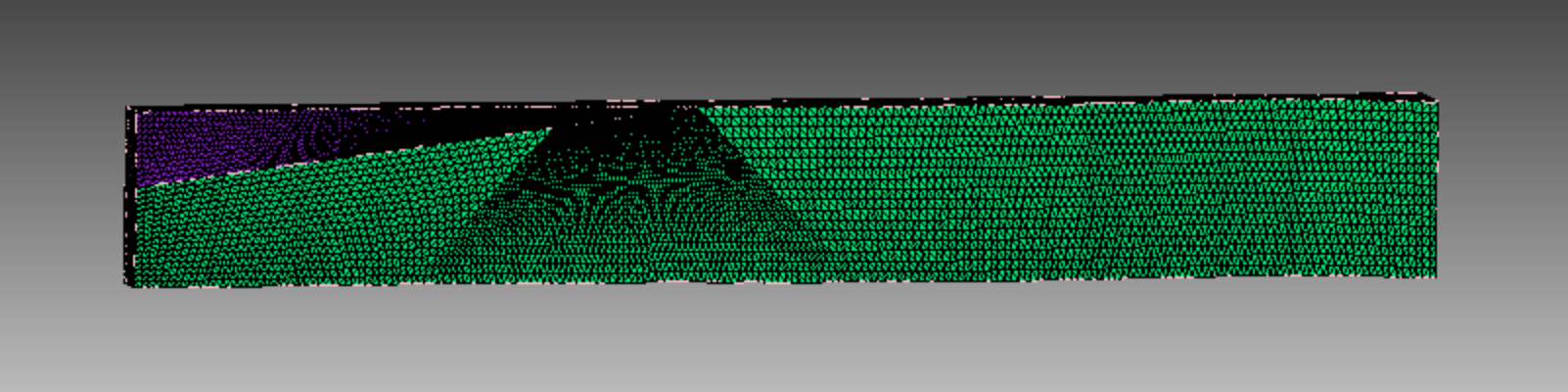
When i look at the quad mesh i would say a good example when the triprim scheme will produce a bad quality. The adjacent surface 52 has a different mesh size and the pave scheme set. Surface 52 is a good rectangle. So i don’t know why you won’t use the map scheme here.
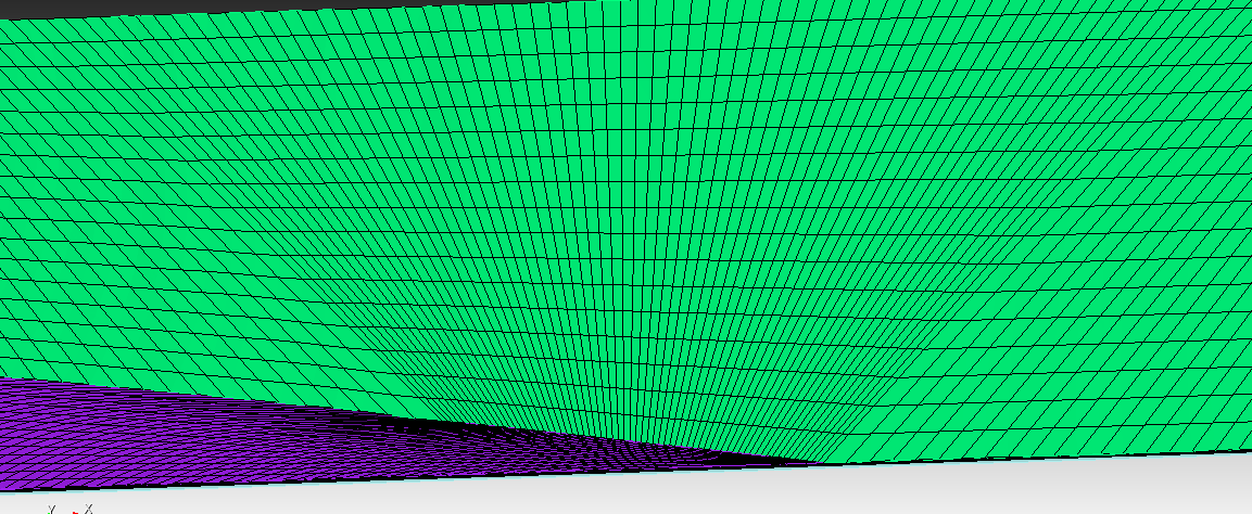
You would already achieve a way better mesh when you don’t set any scheme and let the autoscheme work, or set the pave scheme at surface 53