Converting Leapfrog OBJ/STL (faceted geology) into watertight ACIS solids for hex meshing

Environment

  • Coreform Cubit: 2025.3 (Windows)
  • Geometry source: Leapfrog Geo exports per geologic unit (OBJ primary; STL also tested)
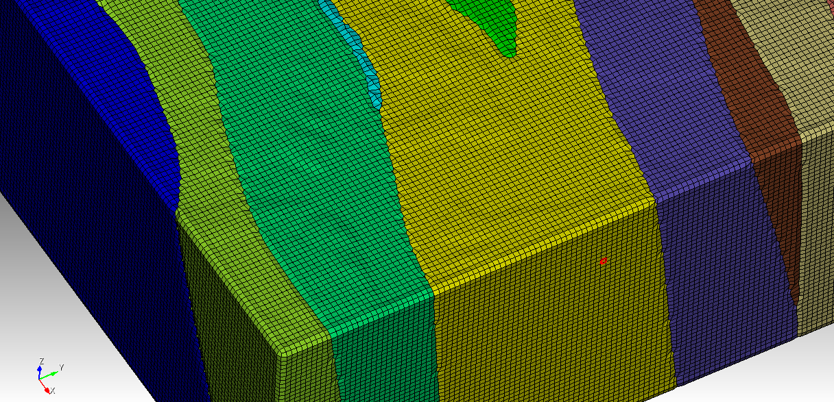
  • Goal: Prepare multiple contacting geological volumes (faults, lithologies, intrusions) as watertight ACIS solids with coincident interfaces, then generate hex-dominant meshes for coupled THM simulations (MOOSE).

What I need (the short version)

  1. The recommended, supported workflow in Cubit 2025.3 to take faceted shells (OBJ/STL exported from Leapfrog) and convert them into closed ACIS volumes suitable for imprint/merge across bodies and hexahedral meshing.
  2. Exact command sequences (with valid Cubit 2025.3 syntax) and tolerance guidance to:
  • Close small gaps / non-coincident edges on import,
  • Convert facet surfaces to ACIS sheet bodies,
  • Stitch sheets into closed solids,
  • Heal geometry so it passes volume creation & meshing checks.
  1. Advice on which import format (OBJ, STL, or DXF) is best in Cubit for this use-case, and any import options (e.g., feature_angle, tolerance, stitch, merge) you recommend.
  2. If the in-Cubit path is not ideal, recommended round-trip (e.g., 3rd-party CAD → STEP/ACIS → re-import to Cubit) and which tool(s) you’ve seen work best for geology meshes.

Representative dataset

Each geologic unit is exported as its own OBJ from Leapfrog (per Seequent’s guidance). Units share boundaries and must be conformal in the final mesh. Example unit name: Bevcon.

What I tried & what happened

A) Direct OBJ → facet geometry, then try to mesh (baseline, just to test)

reset
cd "E:/INRS/obj"
import obj "E:/INRS/obj/bevcon.obj" feature_angle 60
zoom reset
draw volume all
list body
list volume
volume 1 name "Bevcon"
volume 1 size 1000
volume 1 scheme tetmesh
mesh volume 1

Result (key excerpts):

  • ERROR: Invalid input mesh : the triangle number 28710 is ill defined.
  • Multiple >>>>Poor Quality Shape Tri Generated!<<<< warnings.
  • ERROR: Volume 1 meshing unsuccessful using scheme: tetmesh
  • No surface or volume mesh produced; visual remains unmeshed.

B) OBJ import with larger feature angle (to reduce splits)

import obj "E:/INRS/obj/bevcon.obj" feature_angle 135

Still left as facet geometry; meshing fails similarly.

C) Use GUI Power Tools → Diagnose Geometry

On the facet-based import of Bevcon I see:

  • Small Surfaces: ~628
  • Cavities: ~24
    Running suggested fixes from Power Tools often triggers facet-engine limitation errors (see below).

D) STL route + “stitch” on import

I pre-processed the OBJ in MeshLab to clean obvious issues:

  • Remove Duplicate Vertices → removed 9
  • Remove Zero Area Faces → removed 13
  • (Non-manifold repairs reported 0 changes)
  • Laplacian Smooth (10 steps)
  • Decimated to 95% faces still preserves shape (also tried higher decimation ratios)

Then exported as STL and imported with stitching:

reset
import stl "E:/INRS/obj/Bevcon.stl" stitch

Result:

  • Body successfully created.
  • WARNING: Volume generated does not completely close. 3D meshing will not be permitted.
  • 34 facet vertices on model boundary detected that could not be merged.
  • Geometry engine remains Facet.

E) “Create ACIS on import” (developer flag)

reset

set developer commands on

import stl “E:/INRS/obj/Bevcon.stl” feature_angle 60 surface_feature_angle 60 merge stitch create acis

Result (good news / bad news):

  • Body created with fewer surfaces (e.g., 96) — so splitting is reduced.
  • Still: WARNING: Volume generated does not completely close.
  • Still facet engine; export to ACIS fails:
    • ERROR: No geometry exported. Must set geometry engine to another type. Body 1 is of Geometry Engine type facet

F) Convert facet body to surfaces, then try to heal/stitch

reset
import stl "E:/INRS/obj/Bevcon.stl" stitch

create surface from body 1
delete body 1

At this point I expected to have independent surfaces I could heal & stitch into a solid. But:

  • Exporting to ACIS at this point:
  • export acis "E:/INRS/obj/bevcon_surfs.sat" overwrite

WARNING: No Valid ACIS Geometry found for export.

  • Several healing/stitching commands I tried either didn’t apply to facet geometry or returned syntax/availability errors depending on context. This is where I need the exact, supported 2025.3 command set for:
    • merging coincident edges/vertices,
    • removing slivers,
    • tightening gaps,
    • stitching surfaces into a sealed shell,
    • creating a volume from surfaces.

(If there is a supported create ACIS surfaces from facet surfaces command such as copying each facet surface into an ACIS sheet surface, I’d appreciate the exact syntax and a suggested loop or selection strategy.)

Error messages seen (sampling)

  • On tet meshing attempt (facet volume):
    ERROR: Invalid input mesh : the triangle number 28710 is ill defined.
    WARNING: >>>>Poor Quality Shape Tri Generated!<<<<
  • On STL import with stitch:
    34 facet vertices on model boundary detected that could not be merged.
    WARNING: Volume generated does not completely close. 3D meshing will not be permitted.
  • From GUI repairs on facet geometry (Power Tools / Diagnose + fixes), and various repair attempts:
    • ERROR: Faceted geometry currently does not support u-v evaluation requests.
    • ERROR: Option not supported for mesh based geometry.
    • ERROR: Cannot create any composites from passed curves.
    • ERROR: Intermixing real and virtual geometry operations using the current solid modeling kernel is not allowed.
    • ERROR: Failed to remove the specified topology.
    • ERROR: Will not attempt to remove surface #. Owning volume has meshed entities.

(I understand most of these are because it’s still facet geometry; listing here to show the roadblocks I hit.)

What I think I’m missing

  • The exact Cubit 2025.3 pathway to go from facet shellACIS sheet surfacesstitched ACIS solid, including:
    • The right import tolerances and flags (merge, stitch, feature_angle, any tolerance argument on import you recommend),
    • The supported commands for edge/vertex imprint and merge on surfaces that started life as facets,
    • The healing commands that are valid on those surfaces (e.g., heal, healer autoheal, remove slivers … arealimit , etc.) with correct syntax and a sensible order of operations,
    • The stitching step (e.g., create volume surface heal) that you recommend for a typical imported shell like this.
  • Whether there is a built-in surface fitting approach (e.g., “net surface” / NURBS fit of a triangulated patch) that you recommend using inside Cubit for geology-type surfaces before stitching.
  • Whether you recommend a round-trip through a CAD tool (to STEP/ACIS) before Cubit; and if so, which tools/operations most reliably close small holes and produce clean B-rep on triangulated geology. (If this is the best practice, I’m happy to adopt it — just want to confirm from the Cubit side.)
  • Scaling recommendations: I did see “Small models may be subject to geometric inaccuracies.” If scaling up/down during import or before healing helps (e.g., body all scale ), guidance on typical factors would be appreciated.

Constraints & final goal

  • I have many units (each exported as a separate OBJ from Leapfrog). In the final model, shared interfaces must be coincident after imprint/merge, so that a conformal hex mesh can be generated across materials for THM coupling in MOOSE.
  • I can re-export from Leapfrog with different surface resolution per unit if it helps (Seequent suggested: same resolution across all units).
  • I can pre-clean in MeshLab if that meaningfully improves the Cubit import/heal success.
  • Ultimately, I need a repeatable procedure (scriptable journal) to go from OBJ/STLACIS solidsimprint/merge across volumes → hex meshing.

Specific questions

  1. Preferred import format for this geology use-case in Cubit: OBJ vs STL vs DXF (triangulated). Any pros/cons for downstream ACIS conversion and stitching?
  2. Import options & tolerances: What values do you typically recommend for feature_angle, merge, stitch, and any import tolerance setting when closing typical small seams in triangulated shells?
  3. Facet → ACIS conversion:
  • What is the recommended, supported method in 2025.3 to transform facet surfaces into ACIS sheet surfaces?
  • Exact commands to do this in bulk (per surface, per body).
  1. Stitch & Heal sequence: The correct 2025.3 command sequence (and syntax) to:
    imprint all → merge all → remove tiny slivers (area threshold guidance) → stitch / create volume surface heal → final heal/validate on the new volume.
  2. Diagnosing leaks: Best way to visualize “free edges” / open boundary loops on imported shells in 2025.3 so I can confirm where gaps remain and whether stitch/merge improved things.
  3. Scaling: Do you recommend normalizing model scale before healing (e.g., meters vs kilometers), and if so, typical scale factors?
  4. External CAD option: If you recommend a 3rd-party CAD repair (to STEP/ACIS) first, which tool(s) and operations have proven most reliable for triangulated geology before bringing solids back into Cubit?

I can share a small representative unit (e.g., Bevcon OBJ/STL) if that helps reproduce the behavior.

Thanks in advance for concrete guidance and a supported command sequence. My goal is simply to adopt the workflow you consider robust in Cubit 2025.3 for converting faceted geology to ACIS solids and getting to a clean, conformal hex mesh.

— Hadi

Hello @Hadi,
there is not really a way to go from a faceted geometry (or mesh based geometry) to a brep cad, like the acis format, in cubit.

But from what i read, your final goal is a usable hex mesh and that should be doable.

Can you share the files bevcon.obj and Bevcon.stl so that i can take a look.

Do you also have a set of files that represents the multiple contacting geological volumes that you want to “stitch” together.

Hi Norbert — thanks!

Goal. An all-hex, conformal mesh for THM in MOOSE from Leapfrog STL/OBJ geology. Two datasets:

  • Regional (simplified): ~23 units
  • Triangle (local, detailed): ~27 units

We’ll export ExodusII with block IDs per unit and sidesets for the outer box and selected contacts.

I’ve struggled to turn STL/OBJ into closed ACIS solids. If CAD is not required, I’m happy to skip that step if we can reach a conformal hex mesh.

Questions:

  1. For STL/OBJ geology, is your recommended Cubit workflow to:
  • create an outer brick (domain box),
  • imprint/webcut that brick with the imported triangulated geologic surfaces so each unit becomes a separate region,
  • then hex–mesh those regions (map/sweep/hex-dominant as appropriate)?
    If so, which import/cleanup settings do you recommend for the tri-surfaces (e.g., feature_angle, merge, stitch, any “convert to sheet/surface” step), and what tolerances do you advise?
  1. If direct all-hex meshing of these organic shapes is unrealistic, is there a hex-from-grid/voxel path in Cubit you recommend for geology (and any caveats for getting a conformal multi-material mesh)?
  2. Guidance on handling small slivers/holes and open edges when imprinting/stitching facets so we finish with a watertight, conformal interface would be very helpful (typical tolerances, commands, and what to avoid).
  3. Best practices to end up with well-labeled blocks (per unit) and sidesets (outer boundaries/faults) as part of the webcut/mesh workflow.

Due to sponsor IP, I can’t post the full dataset publicly, and I can share the files privately if Coreform has an upload channel/NDA. I would appreciate it if you could provide me with the private upload channel/NDA, so I can provide the files you asked for (Bevcon.obj and Bevcon.stl, plus a couple of contacting volumes).

Extra details if useful: Cubit 2025.8, Windows, units in meters, typical outer-box size ~15–30 km, target hex size initially 100 m (regional) and 25 m (Triangle), willing to coarsen/refine locally.

Thanks again!

Best,
Hadi

Hello @Hadi,
please use https://transfer.coreform.com/ to upload your files.

After the upload there should be a download link that you can send me.
You can write me a message to my forum user account or send me a mail to support@coreform.com

Hi @Norbert_Hofbauer,

Thanks again for your help. I’ve just sent you the files via email (Subject: Links to the uploaded files/folders (Norbert_Hofbauer)) at support@coreform.com
as you suggested.

Best,
Hadi

Hello @Hadi,
i took a look at your files.
You’ve got a picture with all regions. Can you send me the .stl files for all volumes?
Cubit struggles with opening the obj too much.

From what i see the best option is to get all volumes into cubit and try to mesh it with sculpt.

Hi @Norbert_Hofbauer,

Just a quick update to let you know that I’ve sent an email (as a reply to my earlier message titled “Links to the uploaded files/folders (Norbert_Hofbauer)”) to support@coreform.com. It includes the link to download the full set of polished STL volumes as discussed.

Looking forward to your feedback!

Best,
Hadi

Hi @Norbert_Hofbauer,

Just following up to see if you received the email I sent.

Let me know if everything came through correctly and if you’ve had a chance to take a look at them. I’d appreciate any feedback once you’ve reviewed the files.

Best,
Hadi

Hello @Hadi,
sorry for the late reply. The files use a lot of RAM, everything took very long.
A lot of files had some import errors but sculpt could ignore them enough it seems.

Here is a picture of one of the edges just to show you that its working.

Cubit got stuck when it was autocomputing the size of some volumes, so its better to directly assign a size.

The simplest way to mesh this is

#!cubit
reset

#!python
files = []
files.append("Bevcon.stl")
files.append("Val-DOr.stl")
files.append("Valentin.stl")
files.append("Vicour.stl")
files.append("Pontiac.stl")
files.append("Triangle.stl")
files.append("Pascalis-Tiblemont.stl")
files.append("Plug 4.stl")
files.append("Plug 5.stl")
files.append("Lanaudiere.stl")
files.append("La Corne.stl")
files.append("La Motte-Vassan.stl")
files.append("Lamaque.stl")
files.append("Heva.stl")
files.append("Jacola.stl")
files.append("Dubuisson.stl")
files.append("Dunrain.stl")
files.append("East Sullivan.stl")
files.append("Garden Island.stl")
files.append("Bourlamaque.stl")
files.append("C porphyry.stl")
files.append("Cadillac-Piche-Trivio.stl")
files.append("Connell.stl")

for i in range(len(files)):
 cubit.cmd(f"import stl 'C:/Users/offic/Downloads/STL_GeologyUnits_Polished/{files[i]}'")
 vol_id = cubit.get_last_id("volume")

cubit.cmd(f"volume all size 100")
cubit.cmd(f"sculpt volume all")

But that will only get you 1 size for all volumes. So you should use the material feature from sculpt.
Here is a small example

reset
create brick x 1
webcut volume all with plane xplane offset 0 
webcut volume all with plane yplane offset 0 
webcut volume all with plane zplane offset 0 
vol all size 0.05

Sculpt volume all adapt_type 8 adapt_material 2 2 3 0.5 0 0 7 2 0.5 0 0 
#adapt_material 2 2 2 0.5 0 0 7 1 0.5 0 0  
#defines 2 materials (volume 2 and 7)

draw block all

The materials can be easily defined using the adaptive meshing widget from sculpt.

Also be aware that a refinement on boundaries is possible.

You will just have to invest some time and modify the parameters to your liking to hopefully achieve the desired hexmesh.

From the way the geometry looks and the errors i am now sure that sculpt is the only option here.

Hi @Norbert_Hofbauer,

Thank you so much for the detailed explanation and examples — I really appreciate the time and support.

I’ll go through your suggestions carefully and let you know if I run into any issues.

Just to let you know: on my first attempt following your script, Sculpt started running after importing all STL files, but it aborted mid-process with the following message:

ERROR: Problems ordering edges! Geometry may not be watertight...
ERROR: Sculpt Aborted. No mesh was generated. Check log file for details.

The Sculpt log ends with:

Translation Result: Model size exceeds valid box

So it seems the model scale may be causing problems. Do you have any suggestions for addressing this? Should I apply a scale factor or adjust the bounding box manually?

Thanks again for your guidance!

Best,
Hadi

Which Cubit Version are you using and which OS?
How much RAM does your machine have?

I’m working between two systems — one Windows-based and the other running Linux — but the scripts and tests we’ve discussed were all performed on my Windows machine.

  • OS: Windows 11 Home (Version 10.0.26100 Build 26100)
  • Cubit Version: 2025.8
  • RAM: 32 GB installed physical memory

Hi again @Norbert_Hofbauer,

Just wanted to add that I also tested the same Sculpt meshing script on my Linux system, but unfortunately encountered the same issue. In this case, Cubit becomes unresponsive during the process, and I get a persistent popup saying:

“Cubit is not responding.”

Here are the specs for that system:

  • OS: Ubuntu 22.04.5 LTS (Jammy)
  • Kernel: 6.8.0-65-generic
  • CPU: Intel(R) Core™ i7-14700KF — 20 cores, 28 threads
  • Architecture: x86_64
  • Threads per core: 2
  • CPU Frequency: 800–5800 MHz
  • RAM: 62 GiB total (≈45 GiB free at runtime)

I tried running the script on both Cubit 2025.3 and 2025.8. On 2025.3, the program crashes and closes unexpectedly during the STL import process. On 2025.8, it proceeds further but crashes while sculpt_parallel_Volume_20 is being created — the terminal simply returns "Killed" and the window closes. The unresponsive popup appears persistently on both versions during analysis.

Let me know if there’s anything I should try in terms of scaling, memory management, or pre-processing that might help stabilize things.

Thanks again,
Hadi

Cubit becoming unresponsive will happen when it is still busy with a task, that’s normal and happens regularly when working with large stl.

I would say you have not enough RAM. Here is a screenshot from my machine somewhere in the middle of running sculpt.

image

You have to search for a way to get your stl files smaller or move on to a more capable machine.

Hi @Norbert_Hofbauer,

Thank you for the input and the heads-up regarding the RAM requirements! I’ll first try exporting (from Leapfrog) my STL volumes at a lower resolution to reduce file sizes. If the issue persists, I’ll consider switching to a more powerful machine. I’ll be sure to reach out again if I run into further issues.

Thanks again for your continuous support.

Best,
Hadi

Hi @Norbert_Hofbauer,

I am following up on our earlier conversation regarding the meshing of my Leapfrog-derived geological model, and I would greatly appreciate your guidance on a few issues that have arisen as the work progressed.

Since our last exchange, I have had access to a server with significantly more RAM, which resolved the earlier memory-related crashes. With this setup, I successfully ran the Sculpt script you suggested.
This produced a hex mesh for all 23 STL geological units. However, as soon as I ran a mesh quality evaluation, I identified:

  • A substantial number of “bad shear hex” elements, and
  • A non-negligible number of negative Jacobian elements, reported explicitly in the quality report.

Because I am ultimately using this mesh in MOOSE for coupled THM simulations—including plasticity, shear dilation, fluid pressure coupling, temperature gradients, and localization behavior—any negative Jacobians or severely distorted hexes cause solver failures or nonphysical deformation fields. For this reason, I must eliminate or at least localize and repair these problematic elements.

1. Steps attempted to improve hex-mesh quality

Before reaching back out to you, I made several systematic attempts to reduce the negative Jacobians and bad shear hex elements. Despite these efforts, the negative Jacobians remain the main bottleneck preventing THM simulations from running. They included trying smoothing, remove_bad, defeature, etc with different values assigned (to the smooth, remove_bad options). For example:

cubit.cmd(f"sculpt volume all smooth 3 remove_bad 2 defeature 2 min_vol_cells 4")

It helped and removed bad shear hex elements and negative Jacobians, but removed a large portion of the geological model including some of the rock units entirely.

2. Incorporating STL faults (17 surfaces) and defining fault-distance zones

Our THM study requires evaluating:

  • Fault connectivity
  • Fluid-pressure focusing
  • Temperature-dependent weakening
  • Shear and tensile failure likelihood
  • Localized dilation around an evolving fault zone

To accomplish this, we intended to import 17 additional STL surfaces representing faults and, without meshing the faults themselves, compute:

  • The distance from each mesh element to each fault
  • A fault-affected region around each fault separately
  • Assign a unique block/group ID for each fault zone (17 total)

This would allow us to assign mechanical/thermal/hydraulic enhancement factors inside MOOSE using the preassigned element groups.

What we attempted in Cubit:

We tried:

import stl 'fault01.stl'
create distance field from surface <fault-ID> to volume all ...

or scripting Python loops to compute distance fields and generate element sets.

What happened:

  • Cubit refused to compute distances from a facet-only STL surface imported without conversion to ACIS, reporting errors such as:
    • “No valid geometric entities”
    • “Cannot compute distance field on faceted STL surface”
  • Attempts to use surface all or geometry evaluate on STL-derived surfaces also failed due to the lack of an underlying ACIS representation.
  • Some commands were accepted syntactically but produced empty or invalid element groups.

Why this matters:

To proceed in MOOSE, we require 17 separate distance-based zones (one per fault).
If we cannot compute these fault-distance fields in Cubit, we must reconsider whether:

  • The STL faults must be imported into Cubit, or
  • Distance fields must instead be computed entirely inside MOOSE from STL files.

I would be very grateful for your advice on this point.

3. Attempted fallback: tetrahedral meshing

To determine whether the negative-Jacobian issues were unique to Sculpt hex meshing, I also attempted tetrahedral meshing on the server.

The scripts were valid, however the mesher hung on multiple volumes for hours, and frozen at some point.

Target element size (I tried both 50 and 100)

for v in range(1, 24):
cubit.cmd(f"volume {v} size 100")
cubit.cmd(f"volume {v} scheme tetmesh")

Mesh Volumes

for v in range(1, 24):
print(f"— Meshing volume {v} —")
cubit.cmd(f"mesh volume {v}")

4. My questions for you

Given the above, I would deeply appreciate your guidance on the following:

(A) Eliminating negative Jacobians and bad shear hex elements

Is there a recommended workflow—perhaps specific Sculpt parameters, voxel grid adjustments, facet preprocessing, or volume-by-volume strategy—to eliminate negative Jacobians in STL-based geological models created similarly to mine?
I can provide the full quality file, or send you my STL units again, if helpful.

(B) Computing distance-based fault-affected zones

Is there any supported way in Cubit to:

  • Import STL faults without meshing them, and
  • Compute distance fields from STL fault surfaces to the surrounding hex mesh,
  • Creating 17 distinct fault-zone material blocks or element sets?

If not possible with faceted STL surfaces, is there a recommended workaround?

(C) Recommended alternative workflow

If Cubit cannot use STL faults for distance-based zone definition:

  • Would you recommend performing all fault-distance calculations in MOOSE, importing the STL faults after the mesh is generated?
  • Is there a way to bring the geological mesh and STL faults together reliably inside Cubit, even if only to tag elements, without meshing the faults?

5. Summary

  • I now have working Sculpt hex meshes of all 23 STL units (thanks to your initial guidance).
  • However, significant negative Jacobians and bad shear hex elements remain.
  • I also need to incorporate 17 STL faults into the workflow but do not need to mesh the faults.
  • The goal is to assign per-fault zones for THM modeling in MOOSE.
  • Tetrahedral meshing was attempted but is not practical for the full geometry.

Any direction you can provide on these issues—particularly on removing the negative Jacobians and bad shear hex elements and generating per-fault distance zones—would be extremely valuable.

Thank you again for all your help and support.

Best,
Hadi